Facebook
 Google
 GitHub
 Linkedin
Uniqueness Amid Ubiquity: PLZT-Based Capacitors in High-Demand Applications
While capacitors are ubiquitous in electronic designs, PLZT-based capacitors stand out due to their unique characteristics.
Capacitors are arguably the most widely used passive components in electronic designs. Their widespread application includes filters, amplifiers, power supplies, and decoupling components for most integrated circuits. The underlying principle shared by all capacitors is their capacity to store charge, with their effectiveness measured in farads. One farad corresponds to one amp-second per volt, more commonly expressed as one coulomb per volt (1 F = 1 C/V).

Image used courtesy of Adobe Stock
Material Matters: Choosing the Right Capacitor
The variation among capacitors lies in the materials employed in their construction. The chosen material dictates crucial characteristics such as size, capacitance, operating voltage, operating temperature, the usable frequencies of operation, and, of course, cost. Various capacitor types include ceramic, electrolytic, tantalum, polyester, polypropylene, and lead lanthanum zirconium titanate (PLZT).
Capacitors face particularly demanding applications in hybrid and electric vehicles (xEVs). The power delivery system in an xEV comprises the battery (power supply) and the motor (load) where power is consumed. Frequently, multiple loads connect to additional DC rails supplied by switch-mode power supplies (SMPS). These connections are commonly referred to as DC links and almost invariably involve an energy storage element in the form of a capacitor.
In an ideal world, power supplies would be viewed as a constant voltage source. Still, in practical applications, changes in the load and resistances within the system introduce voltage variations, known as transients. Furthermore, DC-to-DC conversion stages commonly employ switching circuits, where additional factors such as bandwidth and parasitic inductances contribute to the observed transients in the system.
When selecting a capacitor for a specific application, its known capacitance serves as a good starting point. However, other crucial factors include operating voltage, temperature resilience, and parasitic elements like equivalent series inductance (ESL) and equivalent series resistance (ESR). The ESL and ESR are pivotal in determining the device’s usable frequency range and self-resonance frequency (SRF). Operating within the specified voltage and temperature limits is crucial to prevent critical damage. Additionally, it’s essential to recognize that the effective capacitance changes both variables. The plots in Figure 1 illustrate how the capacitance of a 1 µF/630 V capacitor fluctuates with operating temperature and voltage.
The data pertains to an EIA 2220-sized Class II ceramic component with a 630 V rating. However, it is helpful to examine the DC Bias Characteristic (top) at 400 V, a more frequently encountered operating voltage. Interestingly, at 400 V, the component functions at approximately 60 percent below its nominal value. The bottom plot depicts the same component under two distinct conditions. The red line illustrates the temperature-induced change at zero bias, while the blue line illustrates the change in capacitance with temperature under a bias of half the rated voltage—specifically, 325 V.


Figure 1. Plots show the change in capacitance over operating voltage and temperature. Image used courtesy of TDK
Operating a typical Class II ceramic capacitor based on barium-titanate at half the rated voltage transforms it from a 1 µF capacitor into a 0.45 µF component. This information holds critical significance in numerous designs, and its impact only worsens when considering temperature variations.
Defying Trends for Enhanced Performance
While this phenomenon holds for multilayer ceramic capacitors (MLCCs) with Class II dielectric, PLZT-based components tend to exhibit characteristic slopes that run in opposite directions. To illustrate this characteristic, let’s take the CeraLink PLZT-based ceramic capacitor family from TDK as an example. The plot in Figure 2 shows that the capacitance predominantly increases with DC bias voltage and operating temperature. In fact, the nominal capacitance aligns closely with its recommended nominal operating voltage levels.

Figure 2. Capacitance change vs DC voltage for the CeraLink PLZT-based capacitor Image used courtesy of TDK
In this particular plot, which is with an operating voltage (V op) of 400 V, the red line shows the capacitance of the PLZT-based capacitor with a very low AC ripple applied; the black line indicates the part with a significant ripple of approximately ±20 V. Both lines start at initial capacitance (C0) and then show performance as DC bias increases to V op and slightly beyond. The graph demonstrates a significant difference at V op between nominal capacitance (C nom) with AC ripple—the peak on the black line, and effective capacitance (C eff) at the same voltage near the peak on the red line.

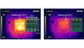
Figure 3. PLZT-based capacitors also demonstrate a notably low equivalent series resistance (ESR). Image used courtesy of TDK
The PLZT-based parts also feature low ESR at higher frequencies (see Figure 3), making them ideal for DC-link capacitors and snubber or filter capacitors in high-voltage and high-temperature applications such as power systems in modern-day xEVs. Here, the capacitors play a comparable role, mitigating the impact of parasitic inductance resulting from extended routes or wire runs.
Positioned close to a switching device, these capacitors aim to address the potential issue of significant voltage oscillations that can occur when the device is turned off. Due to the inherent resistance to changes in current by inductance, an abrupt switch-off can lead to a substantial voltage overshoot, posing a risk of damaging the switching device. In such scenarios, the capacitor supplies the instantaneous current required during a switching event, preventing voltage spikes and potential harm to the switching device.
Similarly, PLZT-based components serve as bus capacitors in applications with elevated temperatures. xEV power systems often demand high power output in such conditions. While current devices like polypropylene capacitors can provide the required energy density, their performance degrades rapidly at elevated temperatures. Consequently, additional thermal mitigation measures become necessary to ensure adequate cooling of the devices. The use of PLZT-based capacitors, however, eliminates the need for a thermal mitigation system, thereby reducing the overall system cost and decreasing the final product’s size and weight.
Adapting to Fast-Switching Trends
PLZT-based capacitors also present an ideal choice for converter topologies based on fast-switching semiconductors like Gallium Nitride (GaN) or Silicon Carbide (SiC). The capacitance equation, [C = I*dt/dV], can be reformulated as [C = I/(dV*f)], where f represents the switching frequency. This expression highlights an inverse correlation between the capacitance requirement and the switching frequency. Nevertheless, when elevating the switching frequency, the ripple current rating of the capacitors used may become the decisive factor in capacitor selection.
A capacitor's constant charging and discharging, coupled with its finite ESR, contribute to an increase in the part’s internal temperature, potentially reducing its rated lifetime. PLZT-based capacitors, however, exhibit an ESR that decreases with rising temperatures, reaching its minimum ESR at higher temperatures. This unique characteristic, combined with a reduction in ESR at higher switching frequencies, enables these parts to attain a notably high ripple current rating and minimal ESR in practical applications.
Efficiency in Consolidation
Multi-chip, PLZT-based capacitor assemblies can reduce the overall number of capacitors needed in a design. The capacitors are generally placed in parallel to achieve the required capacitance within the assemblies. As an illustration, using a 100 nF Class II capacitor at a voltage of 400 V would result in an effective capacitance of 57 nF. Consequently, multiple devices would be required to attain the desired effective capacitance of 100 nF.
Conversely, opting for an 85 nF CeraLink capacitor yields an effective capacitance of approximately 250 nF at 400 V. This surpasses the necessary capacitance, and about four to five Class II barium-titanate-based ceramic chips of the same size would need to be employed in parallel to match the capacitance of a single PLZT-based component. This principle also extends to the current handling capabilities of the capacitors. The PLZT-based part can manage more than twice the current of comparable MLCC-based devices.
PLZT-Based Capacitor Takeaways
While capacitors are ubiquitous in electronic designs, PLZT-based capacitors stand out due to their unique characteristics. Unlike traditional counterparts, they exhibit increased capacitance with DC bias voltage and temperature, making them ideal for diverse applications. The superior performance of PLZT capacitors in mitigating issues like voltage oscillations, coupled with their low ESR at higher frequencies, positions them as essential components in power systems, particularly in xEVs. Their adaptability to fast-switching semiconductor-based converter topologies and high ripple current rating underscores their versatility.
Beyond functionality, using PLZT-based capacitors offers cost-effective solutions by eliminating the need for thermal mitigation systems, reducing overall system costs, and decreasing the size and weight of final products. As multi-chip assemblies, the demonstrated effectiveness in reducing the number of capacitors needed and their enhanced current handling capabilities solidify PLZT-based capacitors as leaders that meet demanding modern electronic design requirements.