Facebook
 Google
 GitHub
 Linkedin
Triac Universal Motor Speed Control Circuit Design Basics
Triac circuits are well-known and commonly used for universal motor speed control. This article presents a basic design for a universal motor speed control circuit.
Unlike an induction motor, a universal motor is easily speed controlled by varying its voltage. The RMS voltage of an AC line can be easily, albeit somewhat crudely, varied by chopping out pieces of the sinusoidal waveform. Modern semiconductor power devices quite easily enable such chopping. A commonly used device for switching AC power loads is the Triac (triode for AC) commonly used for universal motor speed control. The Triac is a type of thyristor and is simplistically modeled as two back-to-back Silicon Controlled Rectifiers (SCR) on one piece of silicon, with each SCR acting to gate a current flow in each direction, hence the triac is an AC switch. The switch is controlled by some small signal applied to its gate terminal. This article presents a basic design for a universal motor speed control circuit.
The First Triac
General Electric first developed the Triac and disclosed in a patent (US3275909) filed in 1963. The Triac is a silicon device with five semiconductor regions with alternate n and p layers implementing an n-p-n-p switch in parallel with a p-n-p-n switch controlled with a common gate signal, so as to form a bidirectional switch. Four quadrants of operation are defined for the triac in terms of the polarity of MT2 and the gate with respect to MT1. The four quadrants are MT2 positive and gate positive, MT2 positive and gate negative, MT2 negative and gate positive, and MT2 negative and gate negative all with respect to MT1. The triac is inherently least sensitive in the mode of MT2 negative and gate positive, so this mode is often not used. In three quadrant Triacs, this trigger mode is suppressed entirely within the device.
Commutation Failure
An issue with Triacs that does not occur with two independent SCRs is that of possible commutation failure. With an inductive load, the current will lag the applied line voltage so as the line voltage crosses zero one of the conducting paths through the Triac will still be carrying current. This load current in combination with the parasitic capacitance of the device can create a false gate signal and retrigger the device through the other SCR path even with no applied gate voltage. A given Triac will have a limit on the maximum rate of rise of off-state voltage (dv/dt) for a given rate of change of commutating current (di/dt). If an application has a dv/dt that exceeds the Triac limit an external filter network, referred to as a snubber, is required to effectively limit the dv/dt that the device sees. Typically, the maximum dv/dt for a triac is at least tens of volts per microsecond, so for a 120 V sinusoidal waveform at 60 Hz spurious triggering is not an issue in normal operation.
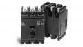
The Triac selected is a BTA216, which is rated for 600 V peak off-state voltage, a maximum continuous current of 16 A, and a peak current capability of 140 A to comfortably handle inductive load switching for motors. The 16 A of continuous current will allow the device to power any load that can be connected to a standard 120 V, 15 A circuit. The critical rate of rise is specified as at least 30 V/μs, so no snubber circuit should be required. The trigger voltage of the BTA216 is specified to be 1.5 V.
Some small signal driving electronics, consisting mainly of a comparator and an analog timer, controls the switch point in the sinusoidal waveform for gating the Triac, which determines how much of the AC wave to "chop out", thus varying the effective voltage to the motor and controlling its speed. A single potentiometer allows the speed control. The circuit schematic for this reference design is shown in figure 1.

Figure 1. Motor Control Schematic. Used courtesy of Blaine Geddes.
Triggering the Triac
An LM311 comparator taps a low voltage full wave rectified version of the 60 Hz AC line and compares this against a small constant DC voltage. The full wave rectified but unfiltered DC signal will look like half sinusoid pulses of the same polarity. Because the reference voltage is quite small, the comparator triggers at a very low voltage value once per half cycle of the 60 Hz line, resulting in an output from the comparator that is a narrow active low pulse, the falling edge of which triggers the LM555 analog timer to produce an output pulse of some variable duration set by the resistor-capacitor time constant of the potentiometer in series with the 0.1 μF capacitor. The time constant ranges from some very small fraction of the 60 Hz cycle to well over 50% of the half-cycle pulse.
The LM555 output triggers the Triac. The LM555 can easily sink the required latching gate current for the BTA216 of up to 40 ma, so it drives the Triac directly. Once a Triac is triggered, it requires that its terminal voltage drop to zero before it turns off, so once triggered, the Triac conducts until the 60 Hz AC power line voltage crosses zero again. The potentiometer varies the time constant. The adjustment range of the circuit allows an output to the motor that ranges from nearly the full 120 V waveform down to a voltage that is well below stall speed for the unloaded motor. Figures 2-4 show waveforms captured on an oscilloscope of the comparator and LM555 for a few potentiometer settings. Figures 5-7 show the chopped AC output for a few potentiometer settings.
/
Figure 2. LM311 output pulse (top) and LM555 timer output (bottom) for a low voltage potentiometer setting. The LM311 output falling edge triggers the LM555 into operation. Used courtesy of Blaine Geddes.

Figure 3. LM311 output pulse (top) and LM555 timer output (bottom) for an intermediate potentiometer setting. The Triac is on during the low state of the LM555 output. Used courtesy of Blaine Geddes.

Figure 4. LM311 output pulse (top) and LM555 timer output (bottom) for near full voltage output. The Triac is on during the low state of the LM555 output. Used courtesy of Blaine Geddes.

Figure 5. AC output to the motor for full speed setting. The noise blips are narrow switching pulses as the Triac is switched off, but then is almost immediately retriggered. Used courtesy of Blaine Geddes.

Figure 6. The AC output for an intermediate speed setting. A significant chunk of the 60 Hz sinusoid is "chopped out" resulting in a drop in the RMS voltage to the motor. Used courtesy of Blaine Geddes.

Figure 7. A relatively low-speed setting where a substantial chunk of the sinusoid is switched off. Used courtesy of Blaine Geddes.
The Triac used is a three-quadrant Triac that can be triggered by a gate signal that is (a) positive with MT2 positive, (b) negative with MT2 positive, or (c) negative with MT2 negative, with respect to MT1. Because of the limitation of the Triac not being able to trigger in the quadrant (gate positive, MT2 negative), the output of the LM555 is referenced to small signal DC positive (VCC) rather than to ground and VCC is tied to MT1 of the Triac, which is also the AC line signal. This may seem a bit counterintuitive, where circuit signals are normally envisioned as referenced to ground, but if MT1 were connected to ground instead of VCC, the three-quadrant operation of the Triac would mean it could only switch once per cycle instead of once per half cycle. The circuit was wired with the neutral of the AC line connected to MT1 to avoid having the hot 120 VAC routed around the card. VCC is approximately 12 volts.
Photo 1 shows the packaged prototype motor controller in its basic bent sheet metal box. The motor to be speed controlled is plugged into the standard 120 VAC receptacle. The intended application of this prototype is speed control for a metal lathe, but the generic receptacle allows any 120 V universal motor, such as those of common handheld power tools, to be connected.

Photo 1. The assembled prototype speed control unit. The variable voltage output is available on the standard 120 VAC receptacle. Used courtesy of Blaine Geddes.
The motor for which this circuit was designed is a series connected universal motor. Series connected motors have a speed that is approximately a linear function of voltage over a voltage range but the speed tends to drop abruptly at a certain threshold. For the application of a lathe power feed, Figure 8 shows the measured feed rate, which is directly proportional to motor rpm, versus RMS voltage from the speed control circuit. At about 86 V this particular motor can't generate enough torque to overcome the basic friction of the drive and it stalls. From about 90 V to 120 V, the motor speed is approximately a linear function of applied voltage. For this application the useful motor speed range is over 10x, allowing infinitely variable feed rates of less than 0.25”/min. to over 2.5”/min.

Figure 8. Measured voltage versus feed rate. Used courtesy of Blaine Geddes.
Triac circuits of the type presented here are well-known and commonly used for universal motor speed control.
References
Grafham, D.R., and Golden, FB (editors), “SCR Manual Including Triacs and other Thyristors,” 6th edition, General Electric, 1979.
Gutzwiller, Frank, General Electric, “Semiconductor Switch,” US Patent #3,275,909, filed Dec. 19, 1963.
BTA216 series D, E, and F, Product Specification, WeEn Semiconductors.
Related Content