Facebook
 Google
 GitHub
 Linkedin
National Electrical Code Basics: Computing Voltage Drop in Branch Circuits and Feeders Part 2
Learn more formulas to calculate voltage drops in single-phase branch circuits and feeders.
To catch up on the rest of Lorenzo Mari's series on computing voltage drop in branch circuits and feeders, follow these links:
- National Electrical Code Basics: Computing Voltage Drop in Branch Circuits and Feeders Part 1
- National Electrical Code Basics: Computing Voltage Drop in Branch Circuits and Feeders Part 3
Some approximate methods suitable to calculate DC voltage drops may apply to AC circuits with small loads, reasonably short, and closely spaced conductors. These methods ignore the effect of line reactance. Yet, its impact on the results may be less than other factors encountered in simple wiring calculations.
Image used courtesy of Pixabay
The Circular Mil
The circular mil (CM) is a measure of the conductor’s cross-sectional area. Figure 1 shows the actual cross-sectional area of a circular conductor A = ΠD²/4 = 3.1416 x D²/4.
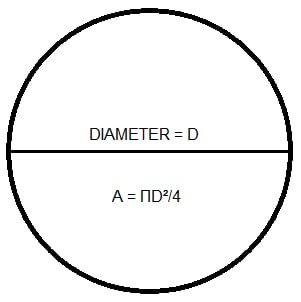
Figure 1. Conductor cross-section. Image used courtesy of Lorenzo Mari
Finding the area in circular mils requires the diameter in mils.
1 mil = 1/1 000 inch = 10ˉ³ inch (in)
By definition, the cross-sectional area of a conductor with a diameter D = 1 mil is 1 CM.
If D = 1 mil, then A = 1 CM = 3.1416 x D²/4 = 3.1416 x ¼ = 0.7854 square mils (sq mils)
sq mils = 0.7854 x CM
CM = 1/0.7854 x sq mils = 1.2732 x sq. mils
Pick a conductor with D = N mils (N = any positive number).
A = 0.7854 x N² sq. mils
CM = 1.2732 x 0.7854 x N² = N²
Then, the area in circular mils of any conductor equals the diameter in mils squared.
ACM = D²
The area in mm² is
Amm² = ΠD²/4 = 0.7854 x D²
Where D = diameter in mm.
NEC Table 8
NEC Table 8 displays standard conductor sizes. It sizes conductors from 18 to 4/0 AWG (American Wire Gage) and from 250 to 2 000 kcmil, copper (uncoated and coated), and aluminum. Sizes 18 to 8 AWG include solid round and stranded conductors. Among other data, Table 8 indicates the cross-sectional area in circular mils, mm², and in.².
Table 8 also contains the conductor DC resistance at 75°C. The NEC’s resistance, reactance, and impedance values are line-to-neutral or ohm-to-neutral.
Example 1.
Find the conductor size of a solid conductor with a diameter of 0.1285 in.
0.1285 in. = 128.5 mil
ACM = D² = 128.5² = 16 512
Table 8 shows CM = 16 510 for size N° 8 AWG.
This problem may be solved by looking for a diameter of 0.128 in. in the column Overall Diameter in Table 8. Observe that overall diameters for stranded conductors are higher than for solid conductors.
Example 2.
Calculate the cross-sectional area in mm² for the conductor in example 1.
D = 0.1285 in x 25.4 mm/in = 3.264 mm
Amm² = 0.7854 x D² = 0.7854 x 3.264² = 8.367 mm²
Table 8 shows an area of 8.367 mm² for a solid conductor N° 8 AWG.
A Formula for Computing Voltage Drop
A typical formula to compute approximate voltage drop in single-phase circuits is
VD = 2 x ρ x I x L / A
where:
A = cross-sectional area of the conductor in CM or mm².
ρ = resistivity of the wire material in Ω CM/ft or Ω mm²/m. ρ is the resistance of a conductor 1 foot long, a cross-sectional area of 1 CM or a conductor 1 m long, and a cross-sectional area of 1 mm² – recall that R = ρL/A.
I = load current (A).
VD = voltage drop (V).
L = distance from source to load in feet or meters.
The constant 2 contemplates the return conductor from the load to the source.
To determine the size of wire that will produce a specific voltage drop, transpose the formula to read
A = 2 x ρ x I x L / VD
Some references state these formulas as
VD = 2 x K x I x L / A
A = 2 x K x I x L / VD
Where K is the conductor resistivity.
Voltage Drop Formulas in English and Metric Units
The resistivity of commercial hard-drawn copper wire at 25°C is 10.895 Ω CM/ft or 0.018113 Ω mm²/m.
The resistivity of commercial aluminum wire at 25°C is 17.345 Ω CM/ft or 0.028834 Ω mm²/m.
It is vital to ponder that the resistance of copper and aluminum increases with temperature due to the augmented molecular movement. The material constants in the following formulas will change with temperature.
English units
2 x K = 2 x 10.895 Ω CM/ft = 21.79 Ω CM/ft
CM = 21.79 Ω CM/ft x I(A) x L(ft) / VD(V) for copper
2 x K = 2 x 17.345 Ω CM/ft = 34.69 Ω cmil/ft
CM = 34.69 Ω CM/ft x I(A) x L(ft) / VD((V) for aluminum
To compute K for every conductor, multiply circular mils by the resistance per foot according to NEC Table 8.
K = CM x Ω/ft = Ω CM/ft
Table 1 shows an average value of K = 12.873 Ω CM/ft considering copper conductors ( Direct-Current Resistance at 75°C).
|
Size AWG or kcmil |
CM |
RDC (Ω/kft) (Stranded) |
K (Ω CM/ft) |
|
12 |
6 530 |
1.98 |
12.929 |
|
10 |
10 380 |
1.24 |
12.871 |
|
8 |
16 510 |
0.778 |
12.845 |
|
6 |
26 240 |
0.491 |
12.884 |
|
4 |
41 740 |
0.308 |
12.856 |
|
3 |
52 620 |
0.245 |
12.892 |
|
2 |
66 360 |
0.194 |
12.874 |
|
1 |
83 690 |
0.154 |
12.888 |
|
1/0 |
105 600 |
0.122 |
12.883 |
|
2/0 |
133 100 |
0.0967 |
12.871 |
|
3/0 |
167 800 |
0.0766 |
12.853 |
|
4/0 |
211 600 |
0.0608 |
12.865 |
|
250 |
250 000 |
0.0515 |
12.875 |
|
300 |
300 000 |
0.0429 |
12.870 |
|
350 |
350 000 |
0.0367 |
12.845 |
|
400 |
400 000 |
0.0321 |
12.840 |
|
500 |
500 000 |
0.0258 |
12.900 |
|
Average |
|
|
12.873 |
Table 1. The average value of K derived from NEC Table 8 data (Copper conductors).
The equation for single-phase circuits using the average value of K will be
2 x K = 2 x 12.873 = 25.746
CM = 25.75 Ω CM/ft x I(A) x L(ft) / VD(V) for copper at 75°C
Table 2 shows an average value of K = 21.182 Ω CM/ft with aluminum conductors.
|
Size AWG or kcmil |
CM |
RDC (Ω/kft) (Stranded) |
K (Ω CM/ft) |
|
12 |
6 530 |
3.25 |
21.223 |
|
10 |
10 380 |
2.04 |
21.175 |
|
8 |
16 510 |
1.28 |
21.133 |
|
6 |
26 240 |
0.808 |
21.202 |
|
4 |
41 740 |
0.508 |
21.204 |
|
3 |
52 620 |
0.403 |
21.206 |
|
2 |
66 360 |
0.319 |
21.169 |
|
1 |
83 690 |
0.253 |
21.174 |
|
1/0 |
105 600 |
0.201 |
21.226 |
|
2/0 |
133 100 |
0.159 |
21.163 |
|
3/0 |
167 800 |
0.126 |
21.143 |
|
4/0 |
211 600 |
0.100 |
21.160 |
|
250 |
250 000 |
0.0847 |
21.175 |
|
300 |
300 000 |
0.0707 |
21.210 |
|
350 |
350 000 |
0.0605 |
21.175 |
|
400 |
400 000 |
0.0529 |
21.160 |
|
500 |
500 000 |
0.0424 |
21.200 |
|
Average |
|
|
21.182 |
Table 2. The average value of K derived from NEC Table 8 data (Aluminum conductors).
The equation for single-phase circuits using the average value of K will be
2 x K = 2 x 21.182 = 42.364
CM = 42.36 Ω CM/ft x I(A) x L(ft)/VD(V) for aluminum at 75°C
Metric units
Following a similar procedure (at 25°C) for single-phase circuits leads to
2 x K = 2 x 0.018113 Ω mm²/m = 0.03623 Ω mm²/m
A(mm²) = 0.03623 Ω mm²/m x I(A) x L(m) / VD(V) for copper, and
2 x K = 2 x 0.028834 Ω mm²/m = 0.05767 Ω mm²/m
A (mm²) = 0.05767 Ω mm²/m x I(A) x L(m) / VD(V) for aluminum
Rather than computing an average value of K for copper at 75°C, let’s calculate K only for a conductor of 500 kcmil, with data from NEC Table 8.
K = 253 mm² x 0.0845 Ω/km /1 000 = 0.021379 Ω mm²/m
2 x K = 2 x 0.021379 Ω mm²/m = 0.04276 Ω mm²/m
A = 0.04276 Ω mm²/m x I(A) x L(m) / VD(V) for copper
Computing K for a conductor of 500 kcmil, aluminum, at 75°C, with data from NEC Table 8.
K = 253 mm² x 0.1391 Ω/km/1 000 = 0.035192 Ω mm²/m
2 x K = 2 x 0.035 Ω mm²/m = 0.07038 Ω mm²/m
A = 0.07038 Ω mm²/m x I(A) x L(m) / VD(V) for aluminum
Formula With Shared English and Metric Units
The following formula combines English and Metric units for copper conductors at 25°C in single-phase circuits.
CM = 70.86 x I(A) x L(m) / VD(V)
These approximate formulas apply to DC and AC circuits with a high power factor, preferably 100%, as is usually the case in residential electrical installations.
Voltage drop calculations in commercial and industrial electrical installations typically require formulas using impedance rather than resistance. Applying the formulas to AC circuits with low power factor loads and significant line reactance may lead to substantial error.
Example 3.
In the circuit of figure 2
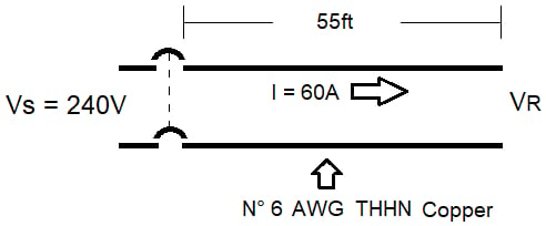
Figure 2. 240V, 2-wire, single-phase circuit. Image used courtesy of Lorenzo Mari
a. Find VD in volt and percentage using English units, at 25°C.
NEC Table 8 shows 26 240 circular mils for conductor N° 6 AWG.
VD = 21.79 Ω CM/ft x 60 A x 55 ft / 26 240 = 2.74 V
VD = (2.74 V/240 V) * 100 = 1.14%
b. Find the receiving-end voltage VR.
VR = Vs – VD
VR = 240 V – 2.74 V = 237.26 V
Example 4.
Repeat example 1 using Metric units at 25°C.
a.
NEC Table 8 shows 13.30 mm² for conductor N° 6 AWG.
50 ft x 0.3048 m/ft = 16.764 m
VD= 0.03623 Ω mm²/m x 60 A x 16.764 m / 13.30 mm² = 2.74 V.
VD = (2.74 V/240 V) * 100 = 1.14%
b.
VR = Vs – VD
VR = 240 V – 2.74 V = 237.26 V
Example 5.
Compute VD in example 1 using the English/Metric formula.
VD = 70.86 x 60A x 16.764 m/26 240 = 2.72 V.
Voltage Drop Tables
There is no need to apply the voltage drop formulas every time. Although there is a lot of software on this subject, it is always practical to have some tables at hand to make quick estimates.
It is vital to understand the basis of the table, such as the formula used, single- or multiple-phase, number of wires, conductor material, AC or DC, magnetic or nonmagnetic conduit, ambient temperature, power factor, and frequency.
Table 3 shows voltage drops for copper conductors according to the formula
VD(V) = 25.75 Ω CM/ft x I(A) x L(ft) / CM, for copper at 75°C
This table uses the Ampere-feet method. The product I(A) x L(ft) becomes a constant read as follows: increasing the current and decreasing the distance in the same proportion, and vice versa, keeps VD constant.
|
Conductor Size |
300 |
250 |
4/0 |
3/0 |
2/0 |
1/0 |
1 |
|
Ampere-feet |
|
|
|
|
|
|
|
|
200,000 |
17.17 |
20.60 |
24.34 |
30.69 |
38.69 |
48.77 |
61.54 |
|
100,000 |
8.58 |
10.30 |
12.17 |
15.35 |
19.35 |
24.38 |
30.77 |
|
90,000 |
7.73 |
9.27 |
10.95 |
13.81 |
17.41 |
21.95 |
27.69 |
|
80,000 |
6.87 |
8.24 |
9.74 |
12.28 |
15.48 |
19.51 |
24.61 |
|
70,000 |
6.01 |
7.21 |
8.52 |
10.74 |
13.54 |
17.07 |
21.54 |
|
60,000 |
5.15 |
6.18 |
7.30 |
9.21 |
11.61 |
14.63 |
18.46 |
|
30,000 |
2.58 |
3.09 |
3.65 |
4.60 |
5.80 |
7.32 |
9.23 |
|
25,000 |
2.15 |
2.58 |
3.04 |
3.84 |
4.84 |
6.10 |
7.69 |
|
20,000 |
1.72 |
2.06 |
2.43 |
3.07 |
3.87 |
4.88 |
6.15 |
|
10,000 |
0.86 |
1.03 |
1.22 |
1.53 |
1.93 |
2.44 |
3.08 |
|
5,000 |
0.43 |
0.52 |
0.61 |
0.77 |
0.97 |
1.22 |
1.54 |
|
4,000 |
0.34 |
0.41 |
0.49 |
0.61 |
0.77 |
0.98 |
1.23 |
|
3,000 |
0.26 |
0.31 |
0.37 |
0.46 |
0.58 |
0.73 |
0.92 |
|
2,000 |
0.17 |
0.21 |
0.24 |
0.31 |
0.39 |
0.49 |
0.62 |
|
1,000 |
0.09 |
0.10 |
0.12 |
0.15 |
0.19 |
0.24 |
0.31 |
|
900 |
0.08 |
0.09 |
0.11 |
0.14 |
0.17 |
0.22 |
0.28 |
|
800 |
0.07 |
0.08 |
0.10 |
0.12 |
0.15 |
0.20 |
0.25 |
|
700 |
0.06 |
0.07 |
0.09 |
0.11 |
0.14 |
0.17 |
0.22 |
|
600 |
0.05 |
0.06 |
0.07 |
0.09 |
0.12 |
0.15 |
0.18 |
|
500 |
0.04 |
0.05 |
0.06 |
0.08 |
0.10 |
0.12 |
0.15 |
Table 3. Voltage drop for copper conductors in a nonmagnetic conduit. Single-phase, 2-wire, and 3-wire, 100% power factor, 60Hz.
Ampere-feet = I(A) x L(ft)
VD(V) = 25.75 Ω x Ampere-feet / CM
Example 6.
Figure 3 shows a 120/240V, 3-wire, single-phase feeder supplying a lighting panel with a 23 kW balanced load. Using Table 3, compute the copper conductor size required for a maximum line-to-line voltage drop of 2% if the run length is 250 ft.
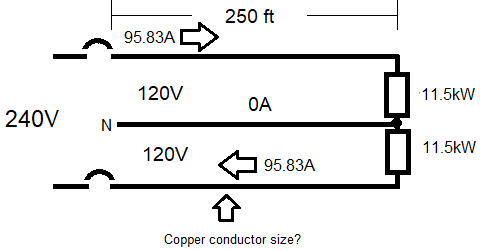
Figure 3. 120/240 V, 3-wire, single-phase circuit supplying lighting load. Image used courtesy of Lorenzo Mari
I = 23 kW/240 V = 95.83 A
L = 250 ft
95.83 A x 250 ft = 23,958 A-ft, say 24,000 A-ft
Maximum VD allowed = 240 x 0.02 = 4.8 V
Table 3 shows VD = 4.88 V in the crossing of the 20,000 A-ft line and size 1/0 column, above the VD required.
VD = 4.84 V in the crossing of the 25,000 A-ft line and size 2/0 column, with a margin of 1,000 A-ft.
Interpolating between 3.87 V (20,000 A-ft) and 4.84 V (25,000 A-ft), the actual VD = 4.64 V (24,000 A-ft) = 1.93%, below the VD required.
Use size N° 2/0 conductors.
Another way to solve the problem with Table 3.
Try size 2/0
24,000 A-ft = 20,000 A-ft + 4,000 A-ft
VD at 20,000 A-ft = 3.87 V
VD at 4,000 A-ft = 0.77 V
Total VD = 3.87 V + 0.77 V = 4.64 V = 1.93%
Use size N° 2/0 conductors.
There are similar tables employing the Ampere-meter method.
Summary
The CM defines a cross-sectional area. One circular mil is the area of a circle with a diameter of 1 mil.
Another expression of the cross-sectional area of a conductor is square millimeters (mm²).
NEC Table 8 provides a good deal of conductor data.
Several formulas allow voltage drop calculations with approximate results in simple circuits. These formulas are helpful in DC circuits and AC circuits with negligible line reactance and high power factor loads.
For most purposes, it is unnecessary to use formulas to determine wire sizes. There are many tables available to do quick calculations. Knowing the basis of the table employed to avoid miscalculations is vital.
Feature image used courtesy of Pixabay
Related Content