Facebook
 Google
 GitHub
 Linkedin
The Next Leap in EV Powertrain Efficiency: The Rise of 3-Level Inverters
Learn the advantages of upgrading from a 2-level inverter to a 3-level inverter for SiC-based EV powertrain designs.
Article co-authored by Fuji Electric's Sebastian Pawusch.
This article is published by EEPower as part of an exclusive digital content partnership with Bodo’s Power Systems.
Battery-powered electric vehicles are evolving rapidly, and nowhere is that progress more visible than in the powertrain. Over just a few years, the industry has moved from early silicon (Si) IGBT traction inverters to silicon-carbide (SiC) MOSFET-based systems that deliver higher efficiency, better thermal performance, and greater power density.
This shift has already redefined what electric vehicles can achieve, shrinking components while unlocking new levels of performance and driving range. Yet, as electric mobility continues to mature, engineers are looking beyond semiconductor improvements to the very topology of the inverter itself, the next leap in powertrain efficiency is now emerging through the adoption of 3-level inverter architectures.
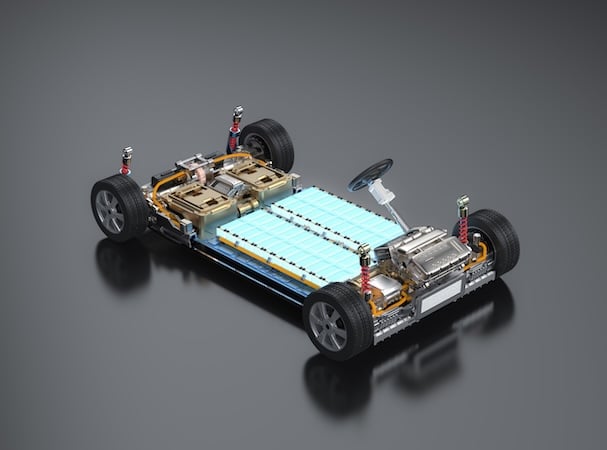
Image used courtesy of Adobe Stock
Shortcomings of 2-level Inverters
Today, the vast majority of battery-electric vehicles rely on a 2-level voltage-source inverter (VSI) to control their traction motors. In this familiar configuration, each inverter leg alternates the DC-link voltage directly between the positive and negative rails, producing a pulse width modulated (PWM) waveform that regulates motor torque and speed. The introduction of SiC MOSFETs has already delivered major benefits compared to traditional Si IGBTs, reducing switching and conduction losses, increasing switching frequencies, and improving thermal behavior. Despite these gains, there are still meaningful opportunities to improve efficiency, particularly in reducing parasitic losses, mitigating electromagnetic interference (EMI), and lessening the electrical stress experienced by both the inverter and motor.
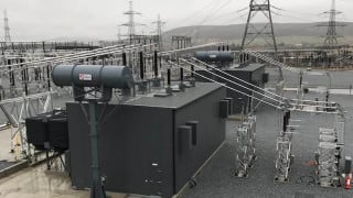
These challenges become more critical as EV platforms move toward higher battery voltages, often 800 V or more in the latest and upcoming generations of vehicles.
In a 2-level inverter, the PWM voltage waveform inherently contains high harmonic content. These harmonics contribute to unwanted copper, iron, and stray losses within the electric machine, converting useful energy into heat. That heat not only reduces efficiency but also limits the duration for which the motor can deliver peak power. Moreover, when high DC-bus voltages combine with the ultrafast switching transitions typical of modern SiC devices, the result is extreme steep voltage slew rates (dV/dt). These rapid voltage changes can wear away motor insulation over time, create bearing currents, and increase EMI, posing significant challenges to long-term reliability, noise, vibration, and overall electromagnetic compatibility.
The 3-level Inverter T-type Topology
To overcome these issues, engineers are turning to multi-level inverter architectures, and particularly the 3-level T-type inverter. This topology introduces a neutral connection and adds two semiconductor devices per phase, effectively splitting the DC-link voltage into two equal halves. The result is that each switching event changes the output voltage by only half the step of a conventional 2-level design. While this adjustment might seem simple, the performance implications are profound. The halved voltage step produces an output waveform that much more closely resembles a pure sine wave, dramatically reducing harmonic distortion and current ripples at the motor terminals.
The effects of this cleaner waveform cascade through the entire system. Lower harmonic content means reduced copper and core losses, as well as diminished eddy-current and hysteresis effects in the motor’s magnetic materials. The machine runs cooler, more efficiently, and more quietly. Torque ripple is reduced, which improves driving smoothness and minimizes acoustic noise, a benefit felt directly by the driver. Meanwhile, the smaller voltage transitions reduce common-mode voltage and dV/dt, dropping the electrical stress on motor insulation and bearings while also lowering EMI emissions. In practice, this means improved reliability, longer component life, and potentially smaller and simpler EMI filters.
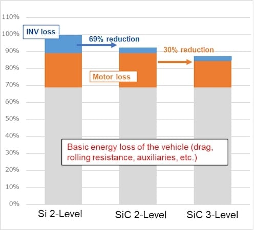
Figure 1. Loss comparison with different inverter topologies and technologies. Image used courtesy of Bodo’s Power Systems [PDF]
Experimental data and simulation results strongly support these theoretical advantages. Studies show that upgrading from a SiC-based 2-level inverter to a SiC-based 3-level T-type inverter can reduce motor-related losses by as much as 30 %, depending on the operating conditions and chosen modulation strategy. At the overall vehicle level, efficiency improvements of around 7 % have been observed, similar in magnitude to the gains realized during the industry’s transition from Si to SiC technology a few years ago. For automakers, such improvements translate into tangible benefits: extended driving range, smaller and lighter cooling systems, or higher sustained power output without compromising reliability.
However, as with any new technology, the 3-level approach comes with its own set of challenges. The added semiconductor devices and gate drivers increase component count and system cost. The control system must also manage voltage balancing across the split DC-link capacitors, which introduces additional sensing and modulation requirements. Advanced pulse-width modulation strategies or redundant switching states are also employed to maintain balance and optimize efficiency. Furthermore, under certain load conditions, the additional devices can introduce slightly higher conduction losses. These design considerations require careful engineering, but ongoing advances in packaging, thermal management, and digital control are steadily reducing their impact.
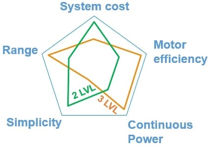
Figure 2. Comparison of key parameters between 2- and 3-Level Inverters. Image used courtesy of Bodo’s Power Systems [PDF]
Higher Efficiency and Lower Power
In the broader context, the move toward 3-level inverter technology aligns perfectly with the industry’s pursuit of higher efficiency and lower EMI as battery voltages rise. It represents a natural next step in the ongoing evolution of the electric drivetrain. Just as the switch from Si to SiC transformed inverter performance, the transition from 2-level to 3-level topologies promises another significant leap forward in range, power density, and system reliability.
Fuji Electric is among the leaders driving this innovation. The company has developed the M1206, a cutting-edge 3-level T-type SiC module designed for 800 V battery systems. The AQG324-certified module integrates all key components into a compact, low-inductance package capable of delivering up to 300 kW of power. This high level of integration simplifies implementation for OEMs, reducing the complexity typically associated with multi-level systems. By offering a ready-to-use, high-performance building block, Fuji Electric is making the adoption of 3-level inverter technology more practical and accessible for next-generation BEVs. With the module expected to reach the market in 2026, the next major improvement in electric vehicle efficiency, range, and overall driving performance is already on the horizon.
This article originally appeared in Bodo’s Power Systems [PDF] magazine and is co-authored by Antonio Poveda Serrano, Automotive Application Engineer, and Sebastian Pawusch, Field Application Engineer Automotive Semiconductors, Fuji Electric
Related Content