Facebook
 Google
 GitHub
 Linkedin
Switching Inductive Loads With a Mechanical Switch
A mechanical switch’s headline current rating is a resistive rating. Switching an inductive load is a different problem, set by the flyback voltage, the arc it strikes, and the contact erosion that follows.
This article is published by EEPower as part of an exclusive digital content partnership with Bodo’s Power Systems.
Power engineers spend a good deal of effort on the energy stored in inductance. Freewheeling paths, avalanche ratings, snubbers, and clamps are routine parts of any switching design, because the voltage a collapsing field produces will destroy a semiconductor left unprotected from it.
The same energy reaches a mechanical switch when one is used to make and break an inductive load, and it does its damage in a way that is easy to overlook. A micro switch or relay contact rated at, say, 6 A 250 V AC carries a resistive rating. Put it in series with a motor, a solenoid, a transformer, or a contactor coil, and its useful life can fall by an order of magnitude.
The clue is on the data sheet. A typical micro switch of this class is rated for around 100,000 mechanical operations but only about 10,000 electrical operations at its full 6 A 250 V AC load. The mechanism is not wearing out ten times faster. The contacts are being eroded by an arc, and the arc is struck by the load’s own stored energy.
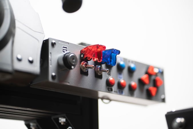
Image used courtesy of Freepik
The Flyback Voltage and the Arc
When the contacts separate and interrupt the current in an inductance, the inductor resists the change according to V = L di/dt. Contact separation forces di/dt to a large value in a very short time, so the voltage across the opening gap rises far above the supply, often to several times it.
The gap between the parting contacts is tiny, and its breakdown strength is low while it is small, so the rising voltage soon exceeds it, ionizes the air, and strikes an arc. Current then keeps flowing across that arc as the contacts move apart, until the stored energy is spent or the gap grows long enough to quench it.
An arc does not sustain at any voltage. It needs a minimum, together with a minimum current, both set by the contact metal; for silver the figures are roughly 12 V and a few hundred milliamps. Below them, no arc can hold, which is why a logic-level switch making and breaking a few milliamps never arcs, and why arc erosion is a problem of real loads rather than of signals.
Above them, the supply decides how hard the arc bites. On AC, the current passes through zero twice per cycle, and the arc has a natural chance to extinguish at each zero crossing, so AC inductive loads are the more forgiving case. On DC, there is no zero crossing. The arc can be broken only by stretching and cooling it as the gap opens, so a DC inductive load holds an arc longer, drives more energy into the contacts, and is markedly harder on them.
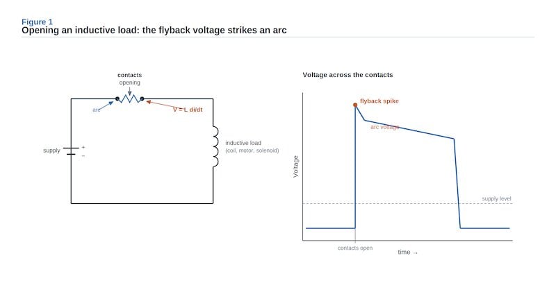
Figure 1. Opening an inductive load. The collapsing field drives the contact voltage far above the supply and strikes an arc across the parting contacts. Image used courtesy of Bodo’s Power Systems [PDF]
How the Arc Erodes the Contacts
Erosion begins before the arc does. As the contacts part, the current crowds into the last shrinking point of contact, which heats, melts, and draws out into a fine molten bridge that ruptures as they separate. That bridge alone transfers a little metal on every operation, which is why material transfer appears even in low-voltage DC switching below the arc threshold. Above the threshold, the arc adds its own damage.
An arc is a plasma at several thousand degrees, and at its roots it melts and vaporizes the contact metal, so the surface loses material and the contact slowly erodes away. On DC, the transfer runs in a consistent direction, building a projection on one face and a matching pit on the other; this pip and crater can eventually interlock or bridge and hold the contacts closed. Arc heat also oxidizes and contaminates the surface, which raises contact resistance and drives local heating higher still.
The end of contact life is some combination of these: resistance climbed out of specification, intermittent making, or a weld that will not release. It is the reason the electrical rating sits so far below the mechanical one. Under load, the arc rather than mechanical fatigue sets the life.
Contact Material
The contact material is the first defense, chosen before any external protection. Fine silver has the lowest resistance but erodes and welds readily under arcing. Silver alloys and silver metal-oxide materials, such as silver nickel or silver tin-oxide, give up a little conductivity for much better resistance to material transfer and welding, which is why contacts meant for real loads are usually made from them rather than from pure silver.
The micro switch referred to here uses a silver alloy contact for exactly this reason. Material sets the baseline, but on its own it does not remove the arc. For that, the design has to handle the energy.
Giving the Energy Another Path
Protecting a contact that switches an inductive load means giving the inductor’s stored energy, ½LI², a path other than the arc, or holding the gap voltage below the level at which an arc strikes.
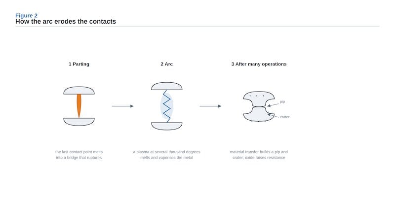
Figure 2. Contact erosion. A molten bridge transfers metal as the contacts part, the arc melts and vaporizes more, and over many operations a pit and crater form while the surface oxidizes. Image used courtesy of Bodo’s Power Systems [PDF]
Three networks cover most cases, and they are the same tools used to protect semiconductors.
An RC snubber, across the contacts or across the load, slows the rate at which voltage rises across the opening gap. The capacitor absorbs energy and limits dV/dt so the gap can widen past the arcing distance before the voltage breaks it down, while the series resistor limits the capacitor’s discharge current when the contacts close again.
As a starting point, the capacitor runs to a fraction of a microfarad per amp of interrupted current and the resistor to an ohm or so per volt of supply, with the resistor chosen above all to keep the make-discharge within the switch’s rating. A snubber suits both AC and DC.
A freewheeling diode across a DC inductive load gives the current a path to circulate and decay after the switch opens, clamping the voltage to about a diode drop above the supply. It is the simplest and most effective protection for DC coils such as relays and solenoids. It cannot be used on AC, where it would conduct every half cycle.
The coil current then decays with the circuit’s L/R time constant, and because a plain diode adds almost no resistance, that decay, and so the coil’s release, is slow; a series Zener or resistor raises the effective resistance and speeds the release at the cost of a higher clamp voltage.
A voltage-clamping device, a metal-oxide varistor or a transientvoltage-suppressor diode across the contacts or the load, conducts above a set voltage and holds the spike to a safe level. A varistor is bidirectional and suits AC, but it absorbs energy on every operation and degrades over its life, so it has to be rated for the cumulative duty.
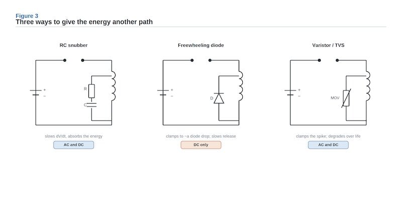
Figure 3. Three suppression networks and where they apply: an RC snubber (AC and DC), a freewheeling diode (DC coils), and a voltage clamp (AC and DC). Image used courtesy of Bodo’s Power Systems [PDF]
Choosing by Load Type
The network follows from the load. For an AC inductive load, an RC snubber or a varistor across the load is the usual answer. For a DC coil, a freewheeling diode is the default, with a series Zener where the release has to be fast, and an RC snubber is a sound alternative.
The network can sit across the contacts or across the load: across the load keeps the transient at its source and avoids dumping the capacitor into the contacts as they close, while across the contacts is simple and common, and either way it is sized so the make-discharge stays within the contact rating. None of this removes the need to choose the switch well. The rating that matters for an inductive load is the electrical rating, not the resistive headline, and the electrical-life figure still has to be read against the real duty once suppression is added.
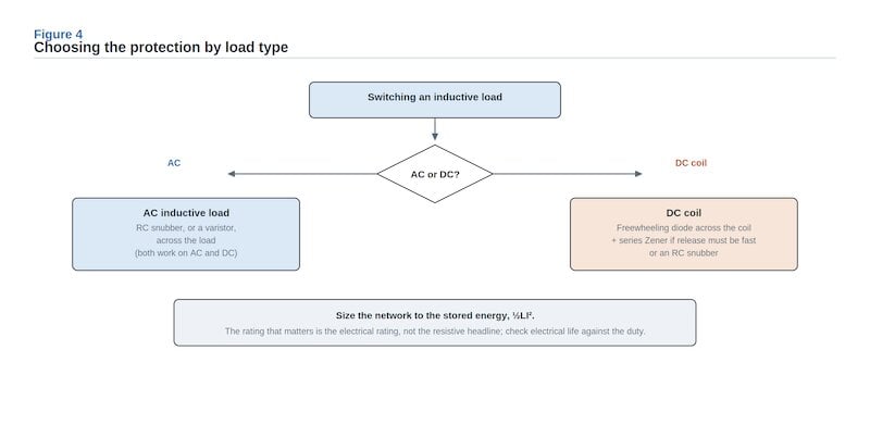
Figure 4. Matching the suppression to the load, sized to the stored energy. Image used courtesy of Bodo’s Power Systems [PDF]
Conclusion
A switch’s headline rating describes the resistive case. The inductive case is a question of energy: the field that collapses when the contacts open strikes an arc, and the arc, with the molten bridge that precedes it, erodes the contacts and fixes the electrical life well below the mechanical one. Handle that energy with an arc-resistant contact and a suppression network chosen for AC or DC and sized to ½LI², and the electrical life stops being the limit it first appears to be.
About the Author

Liu Junxiong. Image used courtesy of Bodo’s Power Systems [PDF]
Liu Junxiong is an R&D engineer at Swiclick, where he leads switch mechanical design and project management. His work focuses on the tactile and electrical performance of miniature and micro switches, including contact materials, contact reliability, and switching performance under real loads.
This article originally appeared in Bodo’s Power Systems [PDF] magazine.