Facebook
 Google
 GitHub
 Linkedin
Substation Components—Part 4: Isolators
This article explains the role of substation isolators, covering their purpose in visible isolation and safe operating sequences with breakers and earthing switches.
Modern high-voltage substations rely on clear functional separation between devices that interrupt current and devices that make equipment safe to touch. Isolators—also called disconnect switches or disconnectors—belong to the second category. They create a visible, verifiable open point so crews can prove de-energization before maintenance, and they coordinate with circuit breakers and earthing (grounding) switches to enforce safe operating sequences.
This article outlines what isolators are designed to do, what they must never do, common configurations you’ll encounter in air‑insulated substations (AIS), and where they fit in busbar switching and earthing schemes.
What Isolators Are For: Visible Isolation and Safe Sequences
At their core, isolators provide a physical, visible break in the conductor path—often an open air gap you can literally see from ground level or via a viewing window—so that qualified personnel can lock out and tag out equipment with confidence. The goal is not current interruption; it’s establishing an unmistakable separation that complements voltage checks and grounding steps during work.
Utilities in North America and internationally favor “visible isolation” because it reduces ambiguity in complex yards with multiple possible backfeeds. When an air-break switch is used for visible isolation, interlocking is typically required to prevent operation under load.
Because isolators are off‑load devices, their correct operation hinges on sequencing with other apparatus. Effective interlocking schemes ensure, for example, that a disconnector cannot be closed or opened while a circuit breaker is carrying load, and that an earthing switch cannot be applied to a live circuit. Many utilities formalize this with both electrical interlocks and trapped-key mechanical systems, designed to be fail‑safe and non‑bypassable without tools.
Interlocking policies from transmission owners such as National Grid (UK) exemplify the practice: they require interlocks between breakers and disconnectors, between disconnectors and earthing switches, and logic to enforce correct busbar transfer sequences.
What Isolators Are Not: Load Interruption
Unlike circuit breakers or load-break switches, isolators do not include arc‑quenching arrangements sized for load or fault interruption. The standard application is “off‑load” after a breaker has removed current. Manufacturers state this plainly: disconnectors isolate equipment from the network and may switch only very small currents or operate when there is no significant voltage change across their terminals. If you require load switching, you need a breaker (or a switch with an interrupter), not a disconnector.
There are narrow exceptions. IEC 62271‑102 includes defined switching capabilities for specific small currents (for example, busbar or line-charging currents under controlled conditions). Even these use cases are bounded by ratings and classes; they do not convert a disconnector into a general load interrupter. When in doubt, treat isolators as isolation devices only and verify any special switching duty against the device’s tested class.
Common Disconnector Configurations in AIS
Substation geometry, clearances, and operating philosophy drive which mechanism you select. The three families below—vertical break, horizontal break, and pantograph—cover the vast majority of AIS layouts, with variations like center‑break, double‑break, and “knee” types optimizing footprint and clearances.
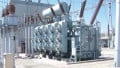
Vertical-Break Disconnectors
A vertical-break unit rotates a blade upward (or downward in underhung designs) to create a vertical air gap between fixed contacts. Because the open gap rises away from grounded steel, vertical-break units can minimize phase spacing and are often chosen where yard width is constrained. Modern designs use sealed bearings and counterbalance systems to improve ice‑breaking performance and reduce maintenance, with ratings ranging from sub-transmission to EHV and options for live-tank earthing attachments.
For example, GE Vernova’s vertical-break family offers models up to hundreds of kilovolts, designed for high short‑circuit withstand and reliable operation in adverse conditions (wind, ice, temperature extremes). These are typical characteristics across major manufacturers and indicate why vertical-break remains a go‑to for compact double‑circuit lines and breaker‑and‑a‑half bays.
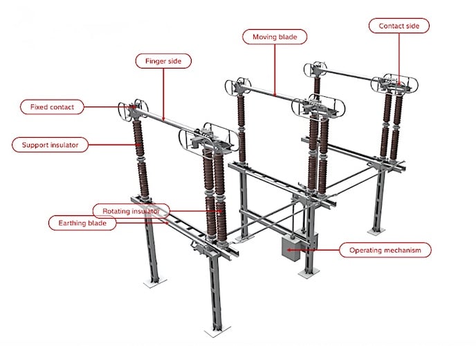
Figure 1. Vertical break disconnector
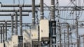
Horizontal-Break Disconnectors
“Horizontal-break” covers center‑break and double‑break patterns where blades part in a horizontal plane. The center‑break style hinges two arms toward the center; it’s simple and economical, but needs more longitudinal space. Double‑break and “knee” or “knee‑type” mechanisms fold the blade on itself, reducing the open length and fitting where vertical clearance is limited. These units are common on line entrances and bus sections in conventional AIS yards.
Horizontal center‑break disconnector up to 245 kV typically supports up to 3150 A continuous and 50 kA short‑time withstand, with contact systems designed for low resistance and ice‑breaking. Double‑break versions extend applicability to 420 kV while limiting footprint, again with short‑time withstand ratings around 50 kA. Such data points help match device class to system fault levels and bus ratings.
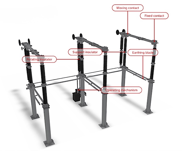
Figure 2. Horizontal-knee disconnector
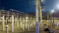
Pantograph and Semi‑Pantograph Disconnectors
Where vertical clearance is limited but you need to connect lower and upper buses, a pantograph (double‑scissor) or semi‑pantograph (single‑arm) is often the most space‑efficient solution. The blade moves in a scissor motion to reach an elevated contact without requiring a tall vertical swing, helping compress the substation footprint.
Manufacturers claim up to about 30% yard space reduction compared with conventional alternatives, and offer versions with integrated earthing switches and pollution‑robust contact designs. Pantographs are common in dense urban AIS, rail traction substations, and EHV yards where phase spacing is tight.

Figure 3. Pantograph disconnector
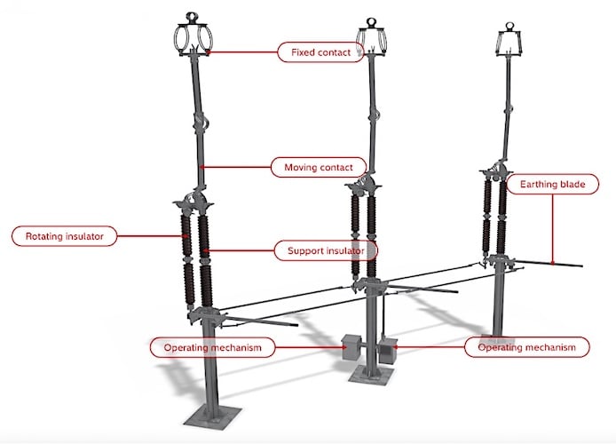
Figure 4. Semi-pantograph disconnector
Applications
Busbar Schemes and Selector Duties
In double‑bus or main‑transfer bus arrangements, isolators enable safe selection of which bus a feeder or transformer connects to—after the breaker has opened the load. In normal operation, a bus coupler (breaker) manages load transfer; isolators provide the visible isolation and the connectivity options to reconfigure bays.
Some standards and guides also define “bus‑transfer current” ratings for disconnectors, used in carefully controlled sequences to shift a bay’s connection between energized buses with minimal disturbance. These ratings are bounded as a percentage of the device’s continuous current, with upper limits depending on system voltage. Engineers must confirm that any disconnector tasked with bus transfer bears the appropriate class rating before writing such steps into the operating procedure.
Earthing Switches and High‑Speed Variants
An earthing switch connects the isolated side of equipment solidly to ground so that induced or trapped charges are safely discharged, and personnel are protected. Earthing switches—often built onto the same frame as the line or bus disconnector—are designed to carry short‑circuit current for a specified time and, in some variants, to “make” onto a fault should an inadvertent live condition exist.
The IEC 62271‑102 family explicitly covers earthing switches alongside disconnectors, including high‑speed earthing switches used for specific applications (for example, in HVDC valve halls or for line de‑energization schemes). As with disconnectors, robust interlocking is essential so that an earthing switch cannot be closed onto a live, non‑isolated circuit.
Medium‑voltage and high‑voltage earthing switches are offered with defined fault‑making capabilities (spring‑stored energy drives to guarantee closure speed) and short‑time withstand ratings aligned with system fault levels. Integrating the earthing function with the disconnector simplifies layouts and ensures the ground can be applied immediately after isolation—subject to mechanical or electrical interlock release.
Interlocking with Breakers and Doors
Beyond device‑to‑device interlocks, many utilities link disconnectors and earthing switches to enclosure doors and access gates. A common requirement is that the main switching device must be open and isolated before a compartment door can be opened, and that an earthing switch must be closed before certain access doors can be unlocked.
Transmission‑level interlocking specifications define these sequences in detail and require fail‑safe behavior and lockable override provisions for maintenance. The objective is simple: eliminate credible paths to incorrect operation that could endanger people or equipment.
Selection and Integration Considerations
Ratings and standards alignment: Begin with IEC 62271‑102 to define the required dielectric withstands, mechanical endurance, and any special switching duties (for example, bus‑transfer or charging currents). In North America, IEEE C37.30.1 complements IEC by specifying requirements for AC high‑voltage air switches rated above 1 kV, including disconnecting, selector, and grounding types.
Continuous and short‑time current: Match continuous current to present and forecasted load, and short‑time withstand to the system’s symmetrical and asymmetrical fault duties at the installation point. Manufacturer catalogs provide typical envelopes (such as 3150 A continuous with 50 kA/3 s short‑time for many 123–245 kV classes). Always verify against the network’s protection studies.
Environmental performance: Ice shedding, wind loading, seismic resilience, and pollution performance (contact design, coatings) differ across mechanisms. Vertical‑break units with counterbalanced blades, knee types with reduced sail area, and pantographs with protected contact systems are all strategies to meet site‑specific constraints.
Footprint and clearances: Yard geometry often dictates the mechanism. If phase spacing is the bottleneck, vertical break may be optimal; if vertical clearance is limited by bus elevations or shielding masts, a knee or pantograph can compress the envelope. Early coordination with civil/structural and bus design guides the choice.
Operating devices and indication: Choose manual or motor operation based on control philosophy and remote operation needs. Positive position indication (mechanical flags plus auxiliary contacts) should be visible locally; for GIS or obstructed views, standards permit reliable position indicators as defined by the standard. Integrate auxiliary switches into SCADA to enforce sequence-of-operations interlocking.
Interlocking and LOTO: Define mechanical key exchanges and electrical interlocks early, especially in multi‑bus yards with complex transfer options. Utility specifications typically require interlocking between breakers, disconnectors, and earthing switches, along with lockable override facilities and unique keying to prevent master‑key vulnerabilities.
Maintenance and Lifecycle: Favor sealed bearings, silver‑plated contacts with self‑wiping motion, and accessible adjustment points to minimize maintenance windows. Many current designs position isolators as “virtually maintenance‑free,” but periodic inspections, contact resistance checks, and drive‑linkage verifications remain good practice.
Key Takeaways
Isolators are the hardware expression of a simple safety principle: prove an open point, then lock it in place. Their value is maximized when they are engineered into the substation as part of a complete sequence—breaker opens the current, disconnector provides the visible gap, earthing switch makes the isolated portion safe, and interlocks ensure no step happens out of order.
Selecting among vertical‑break, horizontal‑break, and pantograph mechanisms depends on geometry, environment, and the operating philosophy you need to enforce. Keep their limitations in view—no load or fault interruption—and rely on current standards and manufacturer data to match ratings and layouts to your system.
All images used courtesy of Hitachi Energy.