Facebook
 Google
 GitHub
 Linkedin
Substation Components—Part 1: Power Transformers
This article explores the role of power transformers in substations, highlighting their design, configurations, cooling methods, tap-changing mechanisms, and insulation systems.
Power transformers are the principal devices used to move energy efficiently through the grid by changing voltage levels to suit the transport or utilization stage. For three-phase balanced systems the instantaneous real power relationship is written in steady-state form as:
$$P = \sqrt{3} V_L I_L \cos (\theta)$$
So raising line-to-line voltage VL for a fixed power P reduces line current IL proportionally and therefore the conduction losses I2R fall quadratically. That is the fundamental economic/thermal rationale behind generator step-up (GSU) transformers at plants and the use of extra-high voltage on long corridors. Conversely, step-down transformers near load centers convert to voltages compatible with insulation, equipment ratings and customer needs while enabling secondary regulation (OLTCs, distribution tap changers, shunt devices) to control service voltage under load diversity.
Transformer ratings, impedance, and vector group choice (phase shift) directly affect:
- short-circuit levels and equipment duty (a low transformer %Z increases prospective fault current that downstream breakers and busbars must withstand)
- voltage regulation under load
- interaction with system protection and coordination (relay reach, selectivity)
Because the transformer is often the first point of isolation/protection between plant and grid, its impedance, tap range and thermal limits are input data for protection, short-circuit, and stability studies.

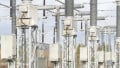
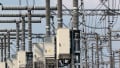
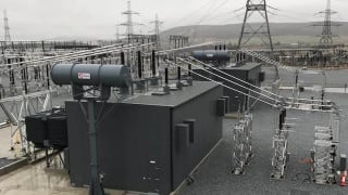
Figure 1. Power transformer. Image used courtesy of Shandong Taikai Power Electronic.
Core Construction and Winding Configurations
Transformer cores are built from thin laminations of grain-oriented silicon electrical steel to reduce eddy-current loss and allow high flux density in the magnetic path. Key construction variables that govern performance are lamination thickness, stacking factor (ratio of solid steel volume to stack volume), lamination coating, and the core geometry (core-type vs shell-type). Laminations are insulated from one another to limit circulating eddy currents; core joints, limb width and window size determine how windings are arranged and influence inter-winding insulation stresses and impedance.
Windings are configured for both electrical requirements and transient behavior:
- Delta–Wye (Δ–Y): common for transmission transformers since Δ on the high-side suppresses triplen harmonic circulation to the source and the Y on the low-side provides a neutral for grounding. The Δ also carries third-harmonic circulating currents and can provide a path for magnetizing inrush asymmetry.
- Autotransformers: share a common winding portion to save copper and reduce losses/weight for the same MVA, but they do not provide galvanic isolation; they also alter short-circuit contributions and fault levels and thus require special coordination.
- Tertiary windings: a delta tertiary is often included to absorb third-harmonic currents, provide auxiliary supplies, and allow connection of station service or motor starting without disturbing main windings.
Winding layout (layer, disc, or helical), conductor selection (aluminum vs copper), insulation systems (paper/oil or modern ester systems), and interleaving all determine short-circuit withstand capability and internal transient distribution (important for impulse stress and for minimizing local overstress between turns). Transformer designers use extensive electrostatic and transient field simulation to ensure that impulse voltage distribution at factory tests stays within material limits.
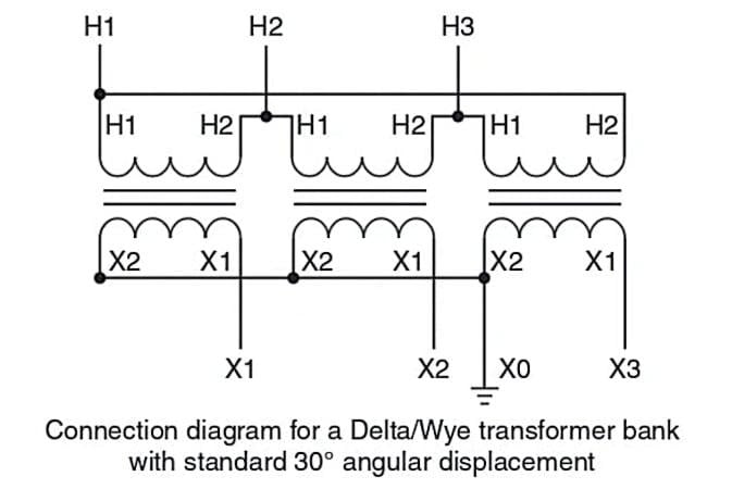
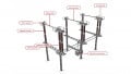
Figure 2. A standard 30° angular displacement delta/wye connection. Image used courtesy of Ahmed Sheikh.
Cooling Methods and Thermal-Rating Impact
Transformer cooling dictates continuous and short-time ratings. As shown in the Table below, standard cooling abbreviations (widely used in IEC/IEEE literature and manufacturer docs) indicate the combination of liquid and external cooling medium and whether the cooling is forced or natural:
| Code | Meaning | Effect on rating |
| ONAN | Oil Natural — Air Natural (self-cooled) | Base rating (nominal) |
| ONAF | Oil Natural — Air Forced (forced-air fans) | Higher continuous rating due to lower oil/coil temperatures |
| OFAF | Oil Forced — Air Forced (oil pumped + forced-air) | Even higher ratings (often used for larger station transformers) |
| OFWF | Oil Forced — Water Forced (water heat exchangers) | Highest continuous rating for compact installations |
Practical implications: forced-oil or forced-air cooling lowers hot-spot and winding temperatures, allowing higher MVA ratings or longer overload capability. Thermal limits are governed by allowable temperature rise of winding insulation (such as 65°C, 85°C or 105°C classes depending on insulation type) and hot-spot allowances defined in standards.
Resonant/residual heating from harmonics and localized hot spots (poor cooling ducts) are common derating drivers. Manufacturers publish temperature rise curves and overload time-hours which are used in asset thermal management and rating studies.
Tap-Changing: OLTC vs Off-Load Tap Changers
Tap-changers change the transformer turns ratio to regulate secondary voltage. There are two principal families:
Off-Load Tap Changers (De-Energized): simple switch arrangements to change the ratio while the transformer is de-energized. Used where taps are changed infrequently (factory setting or planned outages).
On-Load Tap Changers (OLTC): permit ratio changes under load without interruption. OLTCs implement make-before-break (or resistor or reactance bridged) switching between tapped positions to avoid transients; modern designs use diverter switches, resistor transition circuits, and active controls to sequence transitions and minimize arcing. OLTC parameters to specify and tune:
- step size (±% per step, such as ±2.5% total range with 17 steps)
- regulation speed (steps per minute)
- life-expectancy (mechanical operations)
- control logic (voltage-based deadband, droop, or remote SCADA control)
- maintenance and contact wear considerations
OLTC behavior also interacts with system dynamics: rapid tap operation in low-inertia or weak grids can move voltage phasors and must be coordinated with generator AVRs and distribution voltage control schemes.
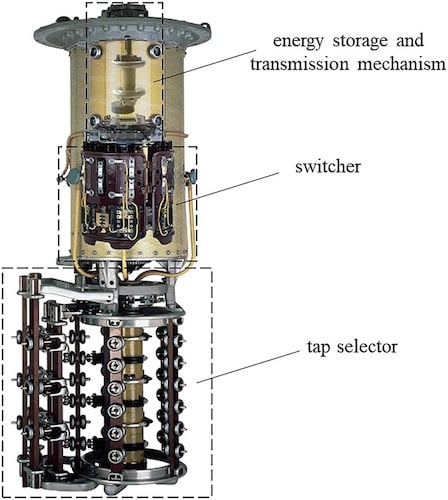
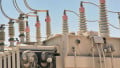
Figure 3. On-Load Tap Changer (OLTC). Image used courtesy of ResearchGate.
Insulation Systems
Insulation selection drives dielectric margins, thermal class and environmental practices. Traditional mineral oil is common for liquid-filled transformers due to good dielectric and thermal properties; ester fluids (natural or synthetic) have superior fire-safety and biodegradability but different dielectric recovery characteristics that affect impulse performance.
Solid insulation (pressboard, Nomex, epoxy) and spacers are chosen by conductor stress, thermal expansion, and partial discharge susceptibility. SF₆-insulated transformer designs are rare but used for compact substations where the tank/enclosure uses SF₆ for insulation; they require gas handling processes and special diagnostics.
Insulation coordination (BIL, switching impulse levels) and surge propagation inside the transformer are fundamental to internal insulation design; factory impulse tests (full-wave and chopped-wave) are used to validate the withstand capability of the insulation system under severe transient conditions.
Key Takeaways
Power transformers are essential in substations, serving as the backbone of voltage transformation and regulation across the power grid. Their design, from core construction to insulation systems, directly influences system efficiency, reliability, and safety. Whether stepping up voltage for long-distance transmission or stepping it down for end-user applications, transformers ensure that electrical energy is delivered economically and within required quality standards.
With advancements in cooling methods, tap-changing technology, and insulation practices, modern power transformers are engineered to handle increasingly complex grid demands, making them crucial for stable operation and enabling effective protection coordination through their impedance, winding, and fault-current characteristics.