Facebook
 Google
 GitHub
 Linkedin
Why Oscilloscope Bandwidth Specs Are Often Misleading for HV Measurement
Oscilloscope bandwidth can quietly change high-voltage transients and hide the real dv/dt stress, not just probe capacitance or ground inductance.
In an earlier article, we discussed how probe capacitance and ground inductance can affect high voltage signal measurements by slowing down signal edges, reducing voltage overshoots, and creating oscillations that are not present in the original circuit. Even if you reduce these probe-related errors, high voltage measurements can still be misleading if you depend too much on the oscilloscope’s bandwidth rating.
In SiC and GaN switching systems, which have fast dV/dt transitions, people often treat bandwidth as a simple cutoff and overlook how the whole system responds. As a result, important transient events and voltage stress conditions can be missed or underestimated, even when the oscilloscope appears to have the right specifications. This article continues the earlier discussion about probes and explains why relying only on the manufacturer’s bandwidth rating is not enough for accurate high-voltage measurements.
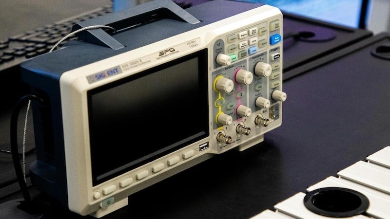
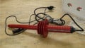
Figure 1. An oscilloscope on a lab bench, reminding engineers that instrument specification alone does not guarantee accurate high voltage transient measurement. Image used courtesy of Pexels.
Bandwidth vs Rise Time in High Voltage-Switching Systems
High-voltage insulation systems are more affected by how quickly the voltage changes than by the highest voltage reached. Fast switching transitions focus electric field stress, speed up charge movement, and activate parasitic components in the system. So, even if the maximum voltage stays within safe limits, a higher dv/dt can cause strong electric fields at insulation surfaces, winding edges, and air gaps.
Electromagnetically, a fast rise time spreads the frequency spectrum of switching events into the tens or hundreds of megahertz. This broad bandwidth energy effectively couples into parasitic capacitances and inductances, which makes it a major cause of both conducted and radiated electromagnetic interference (EMI). Often, EMI control efforts fail not because of high voltage levels, but because the real edge speed was underestimated.
Partial discharge, which is strongly affected by dV/dt, can start localized charges even before the steady-state voltage reaches critical levels, especially in voids, interfaces, and areas with flawed insulation. If the rise time is measured inaccurately or appears slower because of bandwidth limits, early signs of insulation problems may be missed. This is why rise time accuracy is often more important than peak voltage when assessing electrical stress. A small overvoltage with a fast edge can be much more damaging than a higher-amplitude waveform with a slower transition, so edge speed is a key factor in evaluating the real stress on high-voltage components.
Limitations of the 0.35/BW Approximation during High-Voltage Measurement
Oscilloscope bandwidth (BW) is often linked to rise time using a common formula. While this works for an ideal Gaussian measurement system, it is unreliable in high-voltage environments.
$$t_{r(scope)} = \frac{0.35}{BW}$$
The formula assumes a smooth, single-pole frequency response, minimal circuit loading from measurement systems, and a low impedance signal source. But these conditions are rare in real high-voltage switching applications. The high voltage probe adds significant capacitance, and when combined with the high voltage impedance of switching nodes, it slows the edge before the signal reaches the oscilloscope.
Internal parts like protection circuits, isolation barriers, and voltage dividers also create non-ideal frequency responses that are different from the ideal Gaussian model. Because of these system-level factors, the measured rise time is usually determined by the probe and circuit characteristics, not just the oscilloscope’s specification.
Table 1 shows how oscilloscope bandwidth affects rise time accuracy in high voltage switching measurements. It examines a typical SiC switching event with an actual rise time of 10 ns, using the formula to estimate the measured rise time. Even when the bandwidth is ten times higher than the edge frequency, rise time distortion is still visible.
$$t_{r(meas)} = \sqrt{t_{r(true)}^2~+~t_{r(scope)}^2}$$
Where:
$$t_{r(scope)} = \frac{0.35}{BW}$$
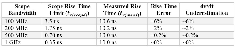
Table 1. Rise-time measurement errors still occur even with large bandwidth margins in fast high-voltage switching systems.
Distortion of High-Voltage Transients with Limited Bandwidth
High-voltage switching waveforms often have fast edges, overshoot, and ringing caused by parasitic elements. If the oscilloscope does not have enough bandwidth, it loses high-frequency detail and changes the shape of the transient, which can give a misleading view of the electrical stress. One issue is artificial edge rounding, which makes transients look slower and causes dV/dt to be underestimated. Limited bandwidth can also lower the apparent peak voltage at switching nodes by hiding short-duration transients. Removing high-frequency components can make EMI seem less severe than it really is, since edge speed is the main cause of broadband emissions.
In high-voltage environments, distorted waveforms can lead to poor design decisions. Hidden overshoot may cause insulation margins to be underrated, while slowed edges can hide partial discharge caused by rapid transients. Snubber circuits designed from inaccurate measurements may also be poorly tuned and fail to handle real switching stresses.
To show how bandwidth affects measurements, the following graph compares a fast high-voltage switching pulse with its bandwidth-limited versions. The example features a sharp 3 ns edge with overshoot and ringing, which are common in modern SiC-based converters. As oscilloscope bandwidth decreases, high-frequency components are gradually lost, making the edge appear slower and causing overshoots and ringing to fade.
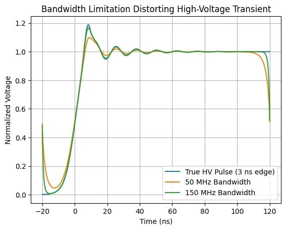
Figure 2. Reduced bandwidth causes captured waveforms to increasingly diverge from the actual transient, concealing peak stress and changing the dynamic behaviour of the switching event. Image used courtesy of Bob Odhiambo.
Measurement System as a Cascaded Transfer Function
Many people see bandwidth as only a property of the oscilloscope, but for high-voltage measurement, the instrument alone does not determine accuracy. Probe cables, isolated components, front-end protection, and the ADC all affect the final waveform. Bandwidth is actually the combined effect of several stages. Each part of the signal chain shapes the frequency response: the probe introduces compensated dividers, cables add distributed capacitance and possible reflections, attenuation circuits add extra poles, and digital filtering can further limit bandwidth.
This is important because many engineers think component ratings add up directly. For example, a 1 GHz oscilloscope with a 200 MHz probe will not give you 1 GHz performance. The probe often sets the overall response, especially with long cables and high attenuation. In practice, bandwidth should be viewed as a system-wide, frequency-domain property. For reliable high-voltage measurement, assess the entire signal path from the switching node to the final digitized waveform, not just the oscilloscope’s stated specifications.
Bandwidth is Only the Beginning of Measurement Error
In high voltage measurement, oscilloscope bandwidth is often seen as a standalone specification, but it is only one part of a complex measurement process. Even with the right bandwidth, accuracy can still be affected by probe placement, ground reference location, or current return path, which can introduce distortion
Besides instrument specs, proper signal sensing techniques also impact measurement accuracy. The next article will cover how sensor placement errors, like ground loop differences and return path issues, can create misleading voltage readings that appear only on the oscilloscope and not in the actual system.
Related Content