Facebook
 Google
 GitHub
 Linkedin
Self-Powered Modules for Measurement and Control in Medium Voltage Power Electronics
Future Medium Voltage Power Electronics solutions for measurement and control require a new approach that increases simplicity, reliability and safety while lowering total costs. Saker has been researching a multifaceted approach to this problem via self-powering.
Future Medium Voltage Power Electronics solutions for measurement and control require a new approach that increases simplicity, reliability and safety while lowering total costs. Saker has been researching a multifaceted approach to this problem via self-powering. We call this technology TrueIsol and it means more than meets the eye.
Stating the problem
The main issue in dealing with MV is the electrical isolation needed to accommodate different system areas that are working at different reference voltages, and even voltages that are floating and have fast varying common modes. In practice this is a two-way problem since it affects both the supply of energy to power a module and the transmission of information, analog or digital to/from a ground referenced central control module. Figure 1 shows the traditional configuration in power electronics to power semiconductor drivers and other control/ measurement modules. The isolation barrier shown will always be limited in dielectric strength and have parasitic capacitances that will show up as unwanted interferences in the control module when high slew rates are involved. Moreover most of the physical distance that separates the central control module and the measurement/control module is joined by copper cables that can pick up electric and magnetic fields in high-voltage high-current switchers.
Also the common mode voltage present in many measurements cannot be easily adapted to ground referenced control electronics. Floating measurements of voltages and currents are an ever increasing necessity with the implementation of cascaded topologies than can handle kV DC buses.

Figure 1: Traditional configuration of measurement and control modules in power electronics.
An example could be the continuous monitoring of Vce saturation voltage in an IGBT as it could provide valuable information about a bond wire lift-off event. Here two problems arise, how to power this monitoring circuit and how to transmit this floating analog measure to a control and monitoring module.
Another example is found in MVDC bus dischargers. If one is to develop a active switched discharger that draws zero current in the off-state and discharges the rail when activated then usually an isolated power supply is needed to overcome the difference in potential between a ground referenced control and the 2-pole floating MVDC rails. With a self-powered approach this isolated power supply would not be necessary.
The copper cables that connect on either side of Fig. 1 the isolated power supply and the digital/analog coupler (optical or capacitive) add weight, cost and increase the risk of ground faults. Optical communication with fibers can be used to increase the limited isolation of traditional couplers, and high voltage switching devices can eliminate the isolated power supply with the self-powering principle.

Figure 2: Long loop primary cable with multiple secondaries concept.
Current Approaches to Powering Floating Modules
Isolated power supplies. The widest available approach to providing energy to a floating module is that of the transformer. High switching frequencies are used to keep core size small and in recent years modules with high rated isolation have appeared in the market. The main drawback is that their size grows as common-mode voltage grows due to isolation requirements.
High-frequency primary loop. This is a particular case of transformer where a cable loop acts as a common primary to many secondaries. The primary consists of a high voltage cable that carries a low voltage high-frequency signal and its wound around a magnetic core. A voltage is induced in the secondary that once rectified and filtered can be used to supply the internal electronics.
In this particular case the insulation between HV and LV parts is provided by the cable carrying the primary high-frequency component. The drawbacks of this arrangement are increased complexity, especially in the case of constant current primary loop control, and radiated EMI from the HV cable loop in the primary that acts as an antenna. This approach is commonly used in drivers for thyristor stacks.
Power over fiber optic or PoF, is a technology in which a fiber optic cable carries optical power which is used as an energy source rather than carrying data. Usually, more than one multimode fiber are used for this purpose. The receiver side is fitted with a photovoltaic unit that will generate electrical current to power up the necessary circuits. This system is however expensive, specially the power laser, the output power of the transmitting device degrades over time, and the output power is limited by the conversion efficiency of the photovoltaic module.
The Concept of Self-powering
Why transfer the energy needed for a certain module through an expensive and bulky barrier with limited isolation when there is enough energy in the MVDC bus rail or in “sub-rails” found in cascaded topologies, this is the main concept of self-powering. The name ‘self-powering may seem misleading to some since the module is still taking the energy from outside of itself, but the main idea is that now the module becomes effectively independent from the rest of the system.

Figure 3: Block diagram of a generic self-powered module attached to an IGBT.
As mentioned not only is the main DC rail a source or energy, but also the floating “sub-rails” found in cascaded topologies, such us the anode-cathode voltage in thyristors or the collector-emitter in IGBTs. The switched nature of these “sub-rails”, varying between the ON saturation voltage and the OFF blocked voltage state, only makes for a lower average effective voltage as seen from the outside. A schematic of this concept for a module that is connected to an IGBT is shown in Fig. 3. The module may have input or output fiber optic connectors to transfer analog or digital data. The main idea however is that now the module floats in the same way the IGBT does and the isolation between the ground-referenced control and IGBT is provided by fiber optics with all their known benefits.
One of the first implications is that the power supply does not need to be isolated which is a great advantage and now suddenly the common-mode at which the module is floating does not really matter neither how fast the common-mode voltage swings.
Properties of Self-powered MV Modules
Future Power Electronic Systems designed with self-powered modules will enjoy advantages over traditional approaches. Some of these are:
1. Makes for an overall distributed solution. Self-powered modules can be considered independent from the rest of the system and thus distributed vs. a centralized solution. Their only interface with the rest of the system should be through fiber cables which can be considered as transparent in the electrical sense. The same characteristics of distributed systems do apply, for example, the independent failure of components without cascading effects.
2. Inherent isolation, improved EMI rejection and measurement CMRR. The only interface between a module performing measurement/ monitoring/control functions should be fiber optics. There are no parasitic capacitances through which fast slew rates can couple. All this allows for increased attenuation against common-mode interference, improved signal integrity in high EMI environments or protection against over-voltage impulses.
3. High-side and low-side solutions. Depending on how the power supply is configured respectively to the rail it is connected to solutions to measure/control/monitor in high-side or low-side configuration are possible.
4. More convenient the higher the common-mode voltage of the module. Traditional powering solutions based on isolated power supplies should be carefully designed based on isolation voltages and slew rate of the common-mode voltage at the secondary. With a self-powered approach, the concept changes and now what matters is only the maximum voltage of the bus at which the modules is connected to. Thus this approach becomes more convenient as the common-mode voltage becomes higher.
5. Less copper, less weight. With self-powered solutions the amount of copper in the system is reduced creating not only cost and weight advantages but also overall safer solutions due to a reduced probability of ground fault events. The weight/size advantage is readily noticeable when high dielectric strengths are required as compared to traditional approaches.
A Multifaceted Research Area
At Saker we started exploring and experimenting with this idea some years ago. After some research and development of prototypes with inherent isolation via the self-powering principle, we realized that the concept itself is more complex and ample than initially expected. From our point of view it is multifaceted and should cover at least the following areas of research:
1. Power supplies. These are non-isolated power supplies with a ratio between input and output voltage >300. Also, the power should be kept very low to keep total dissipation low, to ease protection against input over-voltages and also because the lower the power the more reliable the power supply will be. In some cases, these power supplies also have to withstand the same over-voltages that distribution power frequency lines do suffer. Traditionally the approach and research has focused on isolation for safety and efficiency for energy savings with large output currents. However, the objectives to optimize with these power supplies are different and such are the topologies/ configurations that we have found to be more apt. This area still has room for research and we have developed switched solutions not covered to our knowledge in the available literature. For one, the voltage rating of p-channel semiconductors is severely limited leaving only n-channel devices as viable switchers in power supplies with kV inputs. However, the driving of high-side n-channel MOSFETs and IGBTs conveys extra difficulties, even more, when a 100% working duty cycle is a necessity which makes driving transformers a no viable solution. Also, although the inductor has been used as the core energy transfer device in switchers, capacitive elements could also find room in helping with very high input-output voltage ratio power supplies. Figure 4 shows a prototype of a 2.5kV to 5V all switched approach using two 2-layer boards, shaped to be inserted inside a cylindrical insulator.

Figure 4: 2.5kV to 5V non-isolated switched power supply prototype, external inductor not shown. Input current is kept in the low mA range
2. Low power analog electronics. Having a low power-power supply forces the analog measuring or control designs to run on very little current. Periodic demands in current can be smoothed out by the use of capacitors, but keeping quiescent current as low as possible should be a priority. Nowadays low power digital electronics knowledge is widespread, however very low power analog designs are not that common. Some low-power analog designs even call for non-traditional solutions. For example, ADCs are commonly advertised as low power, with some models consuming a few mW. However, it is not mentioned that the generation of the clock and conversion signals needed to run these parts can take much more power than the ADC itself, so certain applications could enjoy another approach for analog to digital conversions, such as PWM conversion.
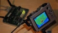
3. High voltage low current fuses. The power supply will be connected to an MV low impedance source, so in the event of a semiconductor failure within the power supply there is still a need to provide protection against a catastrophic event using a fuse. Power supplies used for self-powering modules do (and should) consume very little power, which in practice for a kV input means that the input current is going to be in the mA or even uA range. However low current (<30mA) and high voltage (>3kV) fuses are nonexistent in the market. At Saker we have been researching different approaches to this type of current-limiting fuse. To this purpose we built a HV switch with a 15kV thyratron and a capacitor bank to be discharged through the tested fuse. Although it is an old element, it is easier to build and drive than a similarly rated thyristor stack if only for the lack of clamp requirement. Figure 5 shows the thyratron setup and figure 6 shows the current discharge profile for a certain experimental current limiting fuse connected between the thyratron and the capacitors charged at 6kV. The short reached a peak of 140A and did effectively cut in 1us. The event is so fast that it does not even produce any audible noise. Other approaches with lower peak currents are currently being tried although in practice fuses are tested with a certain X/R impedance ratio that limits the peak currents involved.

Figure 5: Test setup for a 15kV thyratron.

Figure 6: Current profile for an experimental fuse discharge at 6kV rail. Inductive oscillations can be seen at the cut-off tail.
4. Low power optical emitters/receivers. The current commercial offering in optical emitters/receivers does not meet the needs of low power analog designs with self-powering . At Saker we develop our own custom optical emitters/receivers and tailor them to the particular application at hand, for example receivers for simple ON/OFF control functions that run on less than 20uA quiescent current are possible. Not only current drawn by optoelectrical components should be improved but functions also. For example fiber cables are bidirectional, but mostly used in unidirectional way due to lack of commercial dual emitter/receivers in one package. Having the same fiber to transmit and receive can also have advantages from the system simplicity point of view.
We cannot stress enough how important it is to keep overall current consumed by a self-powered module low, as this will affect the size of the power supply, its reliability, the required protections needed to survive over-voltages and most importantly it affects the demands on how to obtain very high ratios (>1000) of input/output voltage.
Applications
Some possible areas of applications are:
1. Dischargers. MVDC switched bus dischargers that are optically controlled and are self-powered from the line that is to be discharged. This greatly simplifies design, cost and the optical isolation provides for virtually unlimited isolation.
2. Driving of semiconductors. Switching on and off of semiconductors could be accomplished by this approach as the blocked state provides enough voltage and energy to provide this function. The trigger signals and others such as error can be supplied by optical means. This solution would not have a practical limit in the number of stackable modules. However it would not suit continuous thyristor triggering in DC applications, unless operation above latching current is provided.
3. MV Sensors. The measurement of both AC and DC is possible with this approach and it would make for an overall cheaper and simpler installation than what is offered nowadays. The solution appeals AC networks for all the drawbacks that casted instruments transformers do have such as weight, ferroresonances and severely limited bandwidth. A direct interface to a control module via digital signals would even save ADC converters.
4. Control and monitoring functions. Various monitoring functions such as temperature or semiconductor saturation voltage monitoring or simple ON/OFF control functions are possible.
5. Power Quality solutions. Taking AC or DC measurements for PQ applications at medium voltage has never been easy due to isolation requirements and the difficulty in making floating measurements. Since self-powered solutions are inherently floating new measurement possibilities are possible in this area.
The development of modules for measurement, control and monitoring based on the self-powering principle for cascaded power electronics topologies brings a new horizon of research. This approach can spawn an array of new modules, lower manufacturing costs, enhance performance and ease system simplicity while increasing overall safety and reliability.