Facebook
 Google
 GitHub
 Linkedin
Isolated Gate Drivers for Modern Power Electronics
One constant in the fast-evolving field of high-powered automotive and industrial electronics is the relentless demand for better efficiency, reliability, and safety. At the heart of power conversion and motion control systems lies a critical component: the isolated gate driver.
This article is published by EEPower as part of an exclusive digital content partnership with Bodo’s Power Systems.
These devices provide galvanic isolation while enabling seamless communication and control, acting as a bridge between low-voltage control subsystems and high-voltage power stages. Their role is indispensable in ensuring system safety as well as energy conversion efficiency.

Image used courtesy of Adobe Stock
In safety-critical applications—like automotive traction inverters, industrial robotics, medical equipment, and medical equipment— the ability to meet rigorous functional safety standards, including Automotive Safety Integrity Level (ASIL) compliance, is paramount. These devices are tasked with precise control of power switches like IGBTs and SiC MOSFETs, safeguarding against faults and maintaining operational integrity under demanding conditions.
At its core, an isolated gate driver performs three essential functions: it provides galvanic isolation, protects power switches, and efficiently controls their operation in conjunction with control units like microcontrollers or FPGAs. By turning these switches on and off with minimal energy loss and in a safe manner, gate drivers can maximize system performance while maintaining stability.
This paper explores the key considerations in selecting a gate driver, using Rohm’s BM6112FV-C as a reference example. With over 15 years of experience, Rohm has become a leader in isolated gate driver integrated circuit (GDIC) development, holding a market leading share in the non-optical isolated gate drivers for automotive traction inverters. The BM6112FV-C exemplifies the many features required by automotive and industrial inverters—one of the most demanding high-voltage, high-powered applications—making it a great example when discussing various design considerations.
Galvanic Isolation
Galvanic isolation refers to the electrical separation between electrical domains, for example, between a high-voltage and a low-voltage domain. This separation is required for safety compliance as well as functional reasons.
From a safety perspective, regulations like UL 1577 and IEC 60664-1 require galvanic isolation to protect against electric shock in systems operating above 60Vdc. In applications where safety is paramount—such as in medical equipment—another layer of isolation is required in case the primary layer fails. When two such isolation layers are implemented as one physical layer, offering equivalent protection, it is called reinforced isolation. This approach provides the same reliability as double-layer isolation but reduces size and cost, making it ideal for designs constrained by space and budget considerations. ROHM’s BD6112HFV-C is BD6112FV-C with reinforced isolation—maintaining the same function, package, and pinout, but includes a second layer of isolation.
Independent of safety reasons, the high voltage domain needs to be galvanically isolated from the low voltage domain for the design to work. This is known as functional isolation. Consider a typical inverter in an electric vehicle (EV) or industrial motor drive inverter operating at 400V-800V and 200A-300A. Switching such high voltage and current at a few to tens of kHz creates electrical disturbances. These disturbances propagate from the power switch side through the ground loop, to the low voltage control subsystem where MCU, SoC, and FPGA reside. Such transient voltages and currents can damage these low voltage devices or cause them to malfunction. This will lead to system malfunctions or catastrophic failures. Galvanic isolation barrier prevents transients to be propagated by effectively cutting off the ground loop between the two power domains.
Testing and certification of isolation barriers are governed by various standards (UL 1577, VDE 0884-10). For example, the BM6112FVC offers 3.75 kVrms rating and is UL 1577 certified. This means it can be used in systems with DC bus voltage up to 891V in Pollution Degree 1 and 2 environments per IEC 60664-1. For lower working voltage, such as those in EVs using a 400V battery, 2.5 kVrms parts would be sufficient as they are safe to be used with working voltage up to 566 VDC. Examples from ROHM’s 2.5 kVrms gate driver lineup include BM6109FV-C and BM6123FV-C.
Types of Isolation Technologies
Isolation can be implemented through various technologies, each with its own strengths and limitations:
- Optical coupling: excellent isolation but relatively slow and performance degrades over time.
- Capacitive coupling: compact, fast, low power consumption, good long-term reliability. Since it operates based on changing electric fields, it is susceptible to strong electric fields.
- Inductive (magnetic) coupling: compact, fast, low power consumption, good long-term reliability. Since it operates based on changing magnetic fields, it is susceptible to strong magnetic fields.
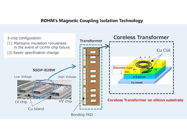
Figure 1. ROHM’s Magnetic Coupling Isolation Technology. Image used courtesy of Bodo’s Power Systems [PDF]
Isolation via capacitive and inductive coupling is the technology of choice for applications which requires size, cost, low power, and excellent performance is maintained over a long lifetime.
Rohm’s Magnetic Coupling Technology
In Rohm’s isolated gate drivers, galvanic isolation is realized with magnetic coupling. One reason for this choice is its high common mode transient immunity (CMTI). Common mode transients are known as the rapid change between the ground voltages on high and low voltage domains. Common mode transients are a serious concern in automotive and industrial systems because it can cause a gate driver’s output to change.
The figure below displays the 3 die in a package constituting Rohm’s magnetic coupling isolated gate drivers—one for the low-voltage input side, one as an isolation barrier, and other for the high voltage output side to the power switch. The magnetic coupling from one die to another is via the on-chip transformer, formed by two coils separated by a SiO2 dielectric layer. The thickness of this layer determines the isolation capability, e.g. 2.5 kVrms, 3.75 kVrms.
Combining process technology and circuit design, Rohm’s magnetic coupling isolation technology delivers:
- Common-mode transient immunity (CMTI) up 200 kV/µs
- 90-ns turn-on and turn-off time
- 30-ns difference between turn-on and turn-off time over operating temperature, making it easy to manage dead time
Additional Factors Which Affect Isolation Requirement and Ratings
Beside the on-chip isolation barrier, working voltage is also determined by creepage, clearance, and operating environment. For example, the 3.75 kVrms rating and associated 891V working voltage is conditioned on the operating environment being Pollution Degree 1 and 2 per IEC 60664-1. There is a dependence on creepage and clearance because electric shorts and arching can happen through, around, and outside of the on-chip isolation barrier. Therefore, the gate driver’s package is also a key consideration. BM6112FV-C is housed in 10 mm x 10.4 mm SSOP-B26CW with industry leading 8.38-mm creepage and 8.6-mm clearance.
Table 1. Key Features and Benefits of the BM6112FV-C
| Feature | Description | Benefit |
| Under voltage lockout (UVLO) | Prevents operation when the gate driver is not properly powered | Protects against erratic behavior and potential damage to power devices |
| Miller clamping | Clamp gate voltage to ground to prevent accidental turn-on due to parasitic coupling from drain/collector to gate | Prevents false turn-on and consequent shootthrough current when both high and low side power switch are on |
| DESAT detection (2 inputs) | Monitors for short and overcurrent conditions; disables the power switch in case of faults | Prevents overheating and protects the power switch |
| Fault output | Provides real-time feedback on abnormal conditions | Enables quick corrective actions and system diagnostics |
| Ready output to MCU | Indicates to MCU when gate driver is ready | Increases functional safety |
| Temperature monitoring | Monitors temperature of power device or module and relay the information to MCU across the isolation barrier | Enhances safety and reliability; reduces BOM cost |
| Output state feedback | Comparison of control input and gate control output to power switch | Critical functional safety feature to ensure the power switch is turned on and off as commanded by MCU |
| Soft turn-of | Gradually disables the power switch during shutdowns | Reduces voltage spikes for lower loss and EMI; reduces stress on power switch and increase reliability |
| Two-level turn-of | Turns off the power switch stronger in the first stage and less strong in the second stage | Quickly relieves stress on the power switch; enhances reliability |
| Negative voltage turn-of | Ensures the gate voltage is well below threshold | Provides faster and more reliable turn-off; can help lower switching loss |
| 20A peak output current | Delivers high output current without requiring external buffers | Simplifies design and layout by using a single gate driver; reduces BOM costs |
| Minimal on/off delay change over temperature and minimal difference between on and off delays | Maintains consistent delay times, with minimal temperature dependence | Improves reliability across varying operating conditions and simplify control of dead time |
In general, requirements increase with altitude, dust, or conductive environments. Users need to consult relevant standards to determine requirements for particular use cases.
Enhancing System Reliability: The Functionalities of Gate Driver ICs
Isolated gate drivers provide more than isolation—they play a key role in the safety, efficiency, and reliability of high-powered systems. Gate driver features are necessary in demanding applications like those in automotive traction inverters and industrial motor drives. The following table below lists several of BM6112FV-C’s capabilities, briefly describing their functions and benefits.
Technology Trends and Next-gen Gate Drivers
As power electronics evolve, gate drivers must evolve to meet increasing demands for performance, efficiency, and reliability. Modern systems in automotive and industrial applications require solutions with higher power densities and integrated functionalities, pushing the boundaries of existing technologies. For example, next-generation gate drivers could enable faster EV charging or compact renewable energy systems, directly addressing the need for greater efficiency and scalability.
The drive for higher efficiency and compact designs has created a demand for gate drivers capable of managing increased voltage and current levels. Devices like Rohm’s BM6112FV-C, with its 3.75 kVrms isolation rating and 20A peak output current, embody this trend. Looking forward, next-generation gate drivers will expand upon these capabilities to support even more demanding applications, such as high-performance EVs and advanced renewable energy systems.
In addition to performance improvements, future gate drivers are expected to incorporate advanced features that streamline system design and enhance functional safety and reliability. Below are a few examples.
SPI interface: supports more comprehensive diagnostic capability to meet functional safety requirements. SPI also makes it easy to configure for specific use cases and to fine tune designs through software changes. This software-enabled configurability can further reduce BOM cost and size by eliminating external components for settings.
Dynamic current-source gate drive control: adjusts gate current dynamically to reduce switching loss.
Built-in self-test (BIST): ensures the integrity of gate driver’s functional blocks and hence its capabilities, helping to achieve ASIL safety requirements at the system level.
Summary
Isolated gate drivers are a critical component in high-powered electronics because they enable or contribute to the safety, reliability, performance, and efficiency of the system. They are used in numerous automotive and industrial products, including traction inverters, chargers, motor drivers, and solar inverters. Using Rohm’s BM6112FV-C as an example, this article discusses key technologies and considerations when selecting and using isolated gate drivers.
BM6112FV-C is referenced because it incorporates a robust set of protection and performance features required for today’s automotive and industrial designs.
For over 15 years, Rohm has been a pioneer in the development of gate drivers for automotive vehicles, earning a reputation for delivering highquality, innovative, and reliable solutions. By collaborating closely with leading OEMs and Tier-1, Rohm has consistently anticipated market trends and developed new technologies that address real-world challenges in automotive and industrial applications. Its next-generation gate drivers will incorporate more programmability and configurability to facilitate development and reduce BOM, support advanced diagnostics to enhance functional safety, and utilize intelligent control to improve efficiency by reducing switching loss.
This article originally appeared in Bodo’s Power Systems [PDF] magazine.