 Facebook
 Google
 GitHub
 Linkedin
Reactors in a Power System
This article highlights two common types of reactors which are the dry-type and the oil-immersed.
In an AC circuit, reactance is the opposition to current flow. A reactor, also known as a line reactor, is a coil wired in series between two points in a power system to minimize inrush current, voltage notching effects, and voltage spikes. Reactors may be tapped so that the voltage across them can be changed to compensate for a change in the load that the motor is starting. Reactors are rated by the ohms of impedance that they provide at a given frequency and current. Reactors may also be rated by the I2R loss across the device at a certain frequency at a rated current.
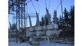
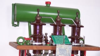
Two common types of reactors are the dry-type and the oil-immersed. The dry-type is open and relies on the air to circulate and dissipate the heat. Dry-type reactors are common in low-voltage applications.
Oil-immersed reactors are common in high-voltage applications. Oil-immersed reactors are placed in tanks and require a magnetic shield to prevent eddy currents from circulating in the tank. The shield is made from laminated steel sheets like the transformer core and motor stators.
Reactors may be used as line or load reactors (see Figure 1). Line reactors are used when low line impedance allows high inrush current, when power factor correction capacitors are used, or when a motor drive causes notching. Load reactors are installed at the output of a motor drive. Load reactors help eliminate voltage spikes or reflected wave noise by slowing down the rate of change in the drive output voltage. However, load reactors have a tendency to overheat due to the harmonic content of the output waveform from the motor drive. The reactor must be designed to reduce the harmonic distortion.

Figure 1. Reactors are used as line or load reactors. Image courtesy of Transcoil
Inrush Current
Many electrical devices draw high currents at startup or have very low impedance to the flow of current. For example, electric motors typically draw many times their full-load current during startup. This inrush current can cause voltage sags that trip out other equipment. Many full-voltage motor starters use reactors to increase the impedance and limit the inrush current. Large capacitor banks used to correct for low power factor have very low impedance when the capacitor bank is first switched ON, and the capacitors begin charging. Low impedance means that the flow of current is very high. A reactor can be added in series to increase the reactance. The increased reactance increases the impedance and reduces the inrush current (see Figure 2).

Figure 2. Line reactors are used to reduce inrush current. Image courtesy of Schneider Electric
Reduced Notching
To reduce notching, the source of the notching needs to be isolated or buffered from other equipment that uses the same power distribution system. Creating a voltage divider is a relatively simple way to minimize notching. See Figure 3. When impedance in the form of a reactor is added in series with an SCR controller, the notch voltage is distributed across the new impedance and the impedance already existing in the feeder lines. The added impedance reduces the notch depth and widens the notch width. Experience has shown that the reactor should have about 3% impedance to reduce the notch depth by about 50%. This is enough to eliminate the extra zero crossovers that cause problems. Higher impedance may cause problems with sensitive equipment because the wider notch may be seen as a loss of voltage. Lower impedance may not reduce the notch depth enough to eliminate the problems.

Figure 3. A reactor can be added in series with an SCR power source to reduce notching.
Note
Transients on a line can cause electronic equipment to generate errors. Digital electronic circuits operate on low-level digital signals that can be corrupted by a false signal induced by the transient voltage.
Saturable-Core Reactors
When an iron core is saturated, substantially all the magnetic domains are aligned with the applied magnetic field. Further increases in the applied magnetic field do not result in increases in magnetic flux. Therefore, there is no increase in the voltage induced in opposition to the change in current. In other words, an inductor loses its ability to oppose changes in current when its core becomes saturated.
A saturable-core reactor is an inductor whose inductance is regulated by a magnetic field produced by a second winding wound around the same iron core as the primary winding. The "power" winding of a saturable-core reactor is the winding carrying the AC load current. The "control" winding of a saturable-core reactor is the winding carrying the DC control current. The control winding is carrying DC strong enough to create a magnetic field that saturates the core.
An increase in DC through the control winding produces an increased magnetic flux in the reactor core. An increase in the magnetic flux moves the reactor core closer to saturation and decreases the inductance of the power winding. A decrease in inductance in the power winding increases the current delivered to the load through the power winding. Therefore, a saturable-core reactor can be used as an amplifier where a relatively small DC through a control winding can control a relatively large AC through the power winding.
In actual practice, a saturable-core reactor consists of two pairs of windings (see Figure 4). The small dots near the saturable-core reactor coils indicate polarity. The power windings are in phase with each other, and the control windings are out of phase with each other. This allows the saturable-core reactor to saturate the core equally in both positive and negative alternations of the AC cycle.

Figure 4. Saturable-core reactors can use a small direct current as a way to control a large alternating current in a power circuit.
Saturable-core reactors were very popular in the plating industry before the advent of DC drives to control the current in the plating solution. In the case of a plater, the part being plated is the load. If no DC is flowing in the control coil, then the IR drop will be controlled by the amount of current in the reactor. With DC current in the control coil, the DC flux will flow in the core and limit the amount of AC flux in the core. Lower AC flux means less reactance and less impedance to the circuit current. Large amounts of AC current can be controlled by a small amount of DC current. This control is very linear and very reliable. Saturable-core reactors have fallen out of use in this type of application because the cost to build a reactor is much higher than building a DC drive.
Note
Saturable-core reactor power supplies used at high power levels are extremely reliable devices because there are no moving parts.
Chokes
A choke, also known as a line choke, is a reactor that is used to limit current to AC or DC drives in the event of short circuits inside the drive. When large short-circuit currents are drawn from the source, the choke starts to build a counter-voltage, and the voltage available to the drive is reduced. The reduced voltage causes the instantaneous electronic trip (IET) circuit to trip the drive off-line to avoid damage. Chokes have large conductors with fewer turns and offer low impedance to the line into the drive.
A common-mode choke is a reactor that reduces common-mode noise current produced by rapid motor drive or device switching (see Figure 5). Load current flows through one winding of the common-mode choke to the load and then flows through the other winding away from the load. This results in two opposite magnetomotive forces that cancel and result in zero inductance. With a common-mode noise, the currents flowing through the two windings of the common-mode choke are in the same direction. Hence, in-phase flux created in each of the windings will add together rather than being canceled as in the case of a differential noise component. This will result in a magnetomotive force that opposes the flow of the common-mode noise.
These common-mode components will flow to the ground as shown in Figure 5. The net result is that a common-mode choke allows the load current to flow almost unimpeded while blocking the flow of common-mode noise current.

Figure 5. Common-mode chokes are used to reduce the severity of drive-induced common-mode noise. Image Courtesy of Power Systems Design
Common-mode chokes are often used to reduce drive-induced common-mode noise. A common-mode choke provides high inductance to oppose common-mode noise currents generated during drive switching. The magnitude and rise time of the noise current are reduced to the point where they are below the noise threshold of affected equipment.
Resonance
Capacitor banks are often used to correct low-power-factor situations. In systems with large amounts of capacitance used to correct power factor, high-voltage distortion can cause resonance at system harmonic frequencies. This results in series-or parallel-resonant currents, which can be very damaging to the electrical system.

Figure 6. A reactor in series with a variable-speed motor drive shifts the resonance frequency away from any harmonics on the line.
Adding a reactor to the incoming power line to the motor drives is a common technique for minimizing the impact of motor drives on other loads in the electrical system (see Figure 6). The added reactance ahead of a motor drive alters the resonance frequency and decreases the amount of distortion in the motor drive's input current.


Understanding the Role of Reactors in Power Systems
Reactor technology plays a pivotal role in modern power systems, particularly in ensuring the efficient and stable operation of electrical networks. This review delves into the critical function of reactors within power systems, highlighting their synergy with transformers to maintain optimal voltage levels across substations.
Reactors are essential components that work alongside transformers to balance reactive power, thereby reducing energy losses during transmission. By managing reactive power effectively, they help in minimizing the operational burden on power systems and enhance overall efficiency.
Moreover, reactors contribute significantly to voltage regulation across various levels of the grid. This capability is crucial for maintaining system stability and ensuring reliable power delivery. The ability to handle fluctuations in voltage ensures that electrical equipment operates within its optimal performance range, thereby extending the lifespan of transformers and other components through reduced stress from voltage changes.
The integration of renewable energy sources, such as solar and wind, presents challenges due to their intermittent nature. Reactors play a vital role in stabilizing these variable inputs, ensuring the grid remains balanced and reliable despite fluctuating power generation levels.
Additionally, reactors help reduce the stress on electrical components by minimizing voltage fluctuations. This stability is particularly important for maintaining equipment longevity and preventing damage from excessive voltage changes.
In conclusion, reactors are indispensable in today’s power systems, offering a blend of functions that enhance efficiency, stability, and reliability. Their role in managing reactive power, regulating voltage, and supporting renewable energy integration underscores their critical importance in the modern electrical grid. This review serves as a valuable resource for anyone seeking to deepen their understanding of reactor functions within power systems.