Facebook
 Google
 GitHub
 Linkedin
Pulsed Inductance Measurement on Magnetic Components from 0.1A to 10kA
Pulse measurement using the Power Choke Tester DPG10/20 series with IGBT power stages has prevailed over other measurement methods for inductance measurement on inductive power components due to its many advantages. The second part of this series of articles explains the two traditional measurement methods (LCR meter with DC bias and reactance determination with mains voltage/mains current) as well as the pulse measurement method using thyristors and demonstrates their inherent disadvantages.
With the exception of air-core coils, all power inductors exhibit a certain saturation behaviour, i.e. the inductance decreases as the current increases. This has to do with the core materials, which lose permeability to a greater or lesser extent from a certain induction B and then, in the extreme case, behave like air. The saturation behaviour of an inductor can be influenced by
- the type of core material
- the core geometry
- the number of turns and
- the air gap.
However, there are often differences between the calculated inductance at a certain current (e.g. the rated current) and the real inductance, because
- there are production spreads of the cores
- the data sheet specifications for the core are imprecise or incomplete
- the inductor geometry causes an inhomogeneous field distribution
- manufacturing tolerances occur
- there are temperature influences.
Therefore, the saturation behaviour L(i) must be measured during the development, manufacture and quality inspection of power inductors.

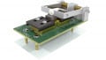
Figure 1: The pulse measurement method of the Power Choke Tester DPG10/20 series was presented in detail in the first part of this series of articles. Image used courtesy of Bodo's Power Systems.
With this measuring principle, a square-wave voltage pulse is applied to the test specimen, as in most real power electronics applications. A current curve is then established in the test specimen, whose slew rate di/dt is dependent on the current-dependent inductance L(i). When the preset maximum current or a preset pulse duration is reached, the measuring pulse is switched off again. Fast IGBT switches are used for this purpose.

Figure 2: Current and voltage curve of the measuring pulse CH1: Current 2A/div CH2: Voltage 50V/div. Image used courtesy of Bodo's Power Systems.

Figure 3: Diagram of the incremental inductance Linc(i) of a Magnetics® High Flux core 58894A2 with 76 turns. Image used courtesy of Bodo's Power Systems.
From the curve of the current i(t) and the voltage v(t) on the test specimen, the following variables can be calculated with a single measuring pulse:
- Incremental inductance Linc(i) and Linc(∫Udt)
- Secant (amplitude) inductance Lsec(i) and Lsec(∫Udt)
- Flux linkage ψ(i)
- Magnetic co-energy Wco(i)
- Flux density B(i), if the core cross-section and number of turns are specified
- Also suitable for 3-phase chokes with the optional 3-Phase Extension Unit
The DC resistance is measured separately. Pulse measurement with switchable IGBT power transistors using the Power Choke Tester DPG10/20 series enables an extremely wide range of applications that cannot be achieved with any other measurement method and any other commercially available inductance meter. The current range of the available models presently extends from < 0.1 A to 10 kA. The pulse energy stored in the choke can lie between a few µJ and 15kJ. The Power Choke Tester DPG10/20 series is therefore suitable for virtually all inductive power components, from small SMD chokes to power chokes weighing several tonnes in the MVA range, e.g.
- smoothing chokes for switch mode power supplies, DC/DC converters, etc.
- filter chokes for UPS, inverters, etc.
- mains chokes for PFC, etc. and commutation inductors
- suppressor chokes and current-compensated chokes
- coils of electromagnets, valve actuators, etc.
- transformers for flyback converters
- motors and power transformers
- and many other inductive components
The device is operated using high-performance software for Windows and is very simple and intuitive to use thanks to a graphic user interface. The measurement results are presented in both graphical and table form. The measurement record is generated in pdf format. The data can be exported and saved in various data formats (XML, CSV).
Table 1: Performance data of the models of the DPG10/20 series


Figure 4: Incremental inductance and secant inductance of a PFC choke with an amorphous tape-wounded core. Image used courtesy of Bodo's Power Systems.

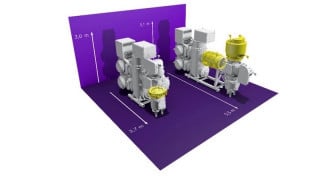
Figure 5: Large reactor for railway applications. Image used courtesy of Bodo's Power Systems.
For routine testing in mass production, the Power Choke Tester DPG10/20 series is easy to integrate into automated test environments by means of a DLL or LabVIEW.
Application examples
This is a single-phase PFC choke with an amorphous tape-wounded core AMCC63 for active 3-phase power factor correction. The rated inductance is 500 µH and the rated current 40 ARMS. The peak value in the application is around 70 Apk at the rated RMS current. The inductance of this choke decreases moderately up to about 60 A (approx. 20%), which is reasonable for an economical design of the choke and does not entail any difficulties in the application.
However, the inductance decreases very quickly after that. At 90 A the choke only has a incremental inductance of 110 µH! Therefore, this choke is not suitable for overload operation, even if shortterm overload operation wouldn't cause any thermal problem for the choke.
In the diagram of the secant inductance, on the other hand, the strong saturation of the core material at currents exceeding 60 A is much less discernible. For that reason, the incremental inductance is generally more meaningful than the secant inductance for power electronics applications.
This example shows a large power choke for a railway application. The rated current is 2100 A and the rated inductance 770 µH. The incremental inductance decreases in the overload range at 4000 A by about 4%.
Other measurement methods
a) Small-signal measurement (LCR meters with DC bias)
The realistic measurement principle is one of the major advantages of pulse measurement using the Power Choke Tester DPG10/20 series. At the same time, it is a major disadvantage of the measurement principle of LCR meters with DC bias. This measurement principle uses sinusoidal voltages and currents with a selectable frequency in the millivolt and milliampere range, which are superimposed on an adjustable DC current. The inductance, resistance and Q factor can then be calculated from the amplitude and phase angle of the voltage and the current through the test specimen.

Figure 6: Small signal measurement of LCR meters (auto balancing method). Image used courtesy of Bodo's Power Systems.
Such a modulation of the core material with tiny hysteresis curves around an operating point cannot be found in real power electronics applications. The measurement result of such a small-signal measurement is accordingly not very meaningful. The difference between these measurement results and those of the DPG10/20 pulse measurement method depend a great deal on the core material and cannot generally be stated for an entire group of materials. In some cases the differences are relatively small, while in other cases they can be considerable.
Due to the large DC bias units required, this method is restricted to low measuring currents (20-200 A) and necessitates very expensive devices.
The generation of an entire measurement curve L(i) takes a relatively long time and thus thermally stresses the test specimen. In the overload range, this can make the measurement of the saturation behaviour impossible due to excessive heating. At least the behaviour cannot simply be measured at defined temperatures, because the temperature is determined by the self-heating.
The pulse measurement method, on the other hand, does not lead to any measurable heating of the test specimen on account of the short pulse duration. The behaviour can thus be determined at any desired temperature, for example, in the climatic chamber.
b) Conventional determination of reactance with mains voltage and mains current
When measuring with mains currents and mains voltages, the rated current and rated voltage (50 Hz or 60 Hz) are usually applied to the test specimen. The RMS values of the current and voltage are measured. According to general AC theory, the inductance is then calculated, neglecting the ohmic resistance, as
\[L = \frac{Vrms}{2\pi f\ast Irms}\]
Taking the ohmic resistance into account, the equation results
\[L = \frac{\left(\sqrt{{\left(\frac{Vrms}{Irms}\right)}^2 - R^2}\right)}{2\pi f}\]
The fundamental problem with this is that no sinusoidal voltages and currents are present due to the extremely non-linear behaviour of the core material. This applies especially to iron core materials, which usually have very much lower permeability at the origin of the B-H curve than in the normal operating range, which then decreases again as the saturation increases.
If sinusoidal currents are applied to the mains choke, a non-sinusoidal voltage results on the test specimen. Conversely, non-sinusoidal currents result if a sinusoidal voltage is applied. In practice, neither sinusoidal currents nor sinusoidal voltages result with this measurement method if an electronically controlled amplifier is not used for the supply. The measured variables feature significant harmonic contents. The normally round sine crests of the current become pointed and in the extreme case even needle-shaped.

Figure 7: Current and voltage shape for a measurement with 50Hz mains voltage, CH1: Voltage 20V/div, CH3: Current 5A/div. Image used courtesy of Bodo's Power Systems.
With such distorted curves, a RMS value measurement of voltage and current and the subsequent calculation of the inductance according to equation (1) or (2) are wrong for two reasons:
- The equations come from the general AC theory. However, this is valid only for sinusoidal variables and linear relationships.
- For the RMS value measurement, the measured variable is by definition quadratically evaluated and integrated over a period.
This is derived from the heating effect of an alternating current in an ohmic resistance. The RMS value of an alternating current is equivalent to the heating effect of a corresponding direct current. This has nothing to do with magnetism! For the current and voltage, this systematically produces overly high values in comparison with the fundamental wave due to the high crest factor.
In principle, therefore, this measurement method is of little use in the non-linear range. Due to a lack of better alternatives, this measurement method was justified in the past, at least up to the saturation limit of the core material. With the advent of the pulse measurement method with switchable power transistors, however, a measurement method is available that is more precise, faster, simpler and, from certain power ratings, also cheaper.
When comparing the measurement results, the conventional measurement corresponds most to the secant inductance Lsec(i) determined with the pulse measurement method (up to the saturation limit). However, the additionally available curve of the incremental inductance Linc(i) can provide further interesting information about the characteristics of the components and the magnetic circuit.
c) Pulse measurement method with thyristors (SCRs)
In the pulse measurement method with thyristors (silicon controlled rectifier SCR that can’t be switched off), only a capacitor is discharged via the test specimen. This produces a damped resonance circuit consisting of the capacitor, the test specimen and a limiting inductor connected in series with the test specimen to protect against short-circuit. The incremental inductance and the secant inductance can then be calculated from the sampled curves i(t) and v(t) in the same way as in the method with switchable IGBTs. Furthermore, the losses and material properties can be calculated from the damped oscillation.

Figure 8: Simplified circuit diagram. Image used courtesy of Bodo's Power Systems.
However, this method has a serious disadvantage, because only one measuring parameter can easily be set – namely the charge voltage of the capacitor.
The oscillation frequency depends only on the capacitance or inductance of these components and cannot be influenced. Hence, the pulse width also cannot be influenced.
A stepless change of the capacitance of the capacitor would be necessary in order to change the oscillation frequency. Even a coarsestepped adjustment of the capacitance is so complex that an automatic adjustment with an appropriate step size can probably never be reasonably accomplished.
Hence, the measurement usually doesn't take place with the correct frequency (and voltage curve form) that is intended for the test specimen in the real application. The calculation of the losses on the basis of the decay behaviour, which is theoretically possible with this method, is thus cast into doubt, as this is of course also frequency-dependent.
As the entire energy stored in the capacitor is always discharged into the test specimen, this limits the area of application enormously. The maximum measuring current and the pulse energy can only be influenced by the voltage. Here, too, it would be necessary to adjust the capacitance over a very wide range for differently sized test specimens that require a low or a high pulse energy. On the other hand, the measurement method using the Power Choke Tester DPG10/20 series with switchable IGBTs enables easy adjustment of the pulse energy simply by selecting the adjustable parameters measuring voltage and measuring current by up to ten orders of magnitude!
Calibration
The calibration of an inductance meter that can supply measuring currents up to > 10000 A is a big challenge. Inductance standards for such high pulse currents are not commercially available. The inductance standards normally used in calibration laboratories are only suitable for low currents and their resistance is much too high.
Calibration using only a static or dynamic measurement of the accuracy of the voltage and current measurement is not permissible. It leads to incorrect results. The linearity and the pulse behaviour of the complete signal chain and dirt effects play a decisive role, so that conclusions about the accuracy of the inductance measurement cannot be drawn from the static accuracy of the voltage and current measurement.
For that reason ed-k has developed its own inductance standards, which have been optimised to suit the special requirements of the measuring principle. These include a current-independent inductance (saturation-free), a sufficiently low ohmic resistance, and frequency independence of the inductance and the resistance over a wide frequency range.
In order to make it possible for overseas customer to have a calibration carried out by a local calibration laboratory or to do it themselves, ed-k has developed a calibration kit that contains not only the necessary inductance standards, but also corresponding resistance standards and calibration instructions. In Europe, however, the manufacturer's calibration service is more cost-effective and includes a much more extensive test.
Summary
Pulse measurement using the Power Choke Tester DPG10/20 series with fast IGBT switches has great advantages over other measurement methods:
- Enormously wide range of applications. It is suitable for almost all types of inductive power components from small SMD chokes to power chokes weighing several tonnes in the MVA range.
- Very wide current range, currently available from < 0.1 A to 10000 A
- Pulse energy currently available from µJ to 15 kJ
- Suitable for all core materials from many hundreds of kHz to < 5 Hz
- Small, light and relatively inexpensive despite the very high measurement currents
- Very simple measurement, measurement results within seconds
- No thermal influence on the test specimen
- Also suitable for 3-phase chokes
Conclusion
Due to the enormous restrictions, the pulse measurement method with silicon controlled rectifiers (SCRs) is not well suited for inductance measurement and is not in widespread use.
Only the pulse measurement using the Power Choke Tester DPG10/20 series with switchable IGBTs enables measurement of the inductance with the same voltage, the same curve form and the same pulse width as in the real application. Hence, it provides more realistic measurement results than the other measurement methods and has prevailed in many sectors on account of its enormously wide range of applications and numerous other advantages.
This article originally appeared in Bodo’s Power Systems magazine.