Facebook
 Google
 GitHub
 Linkedin
Pulsed Inductance Measurement on Magnetic Components
For inductance measurement on inductive power components, the innovative pulse measurement method of the Power Choke Tester DPG10/20 series, which is based on high-performance IGBT power stages, has established itself. This three-part series of articles explains the different measurement methods and shows the many advantages inherent in the principle compared to the traditional measuring methods and the recently propagated pulse measuring method with thyristors.
In the first part, the pulse measurement method of the Power Choke Tester DPG10/20 series is explained in detail.
Introduction
In 2002, ed-k was the first manufacturer to develop and produce a commercial inductance meter based on the pulse measuring principle with turn-off power transistors (IGBT). Since then, ed-k has been the technical leader in this field. In the meantime, ed-k's Power Choke Tester DPG10/20 series has established itself worldwide as the quasi-standard for the development, production, and quality control of inductive power components.

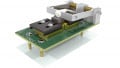
Figure 1. Power Choke Tester DPG10/20 series. Image used courtesy of Bodo’s Power Systems
Principle of pulse measurement of the Power Choke Tester DPG10/20 series
With this measuring principle, a square-wave voltage pulse is applied to the test specimen, as in most real power electronics applications. A current curve is then established in the test specimen, whose slew rate di/dt is dependent on the current-dependent inductance L(i). When the preset maximum current or a preset pulse duration is reached, the measuring pulse is turned off. Fast IGBT switches are used for this purpose.

Figure 2. Simplified circuit diagram. Image used courtesy of Bodo’s Power Systems
The pulse energy comes from a capacitor bank. If its energy content is significantly higher than the energy stored in the inductor under test at the desired maximum measuring current, the voltage of the measuring pulse is roughly constant. Due to the operating principle, there is no upper limit for the capacitance of the capacitor bank, regardless of the type of test specimen, which is one of the reasons for the extremely wide range of applications for almost all inductive power components.

Figure 3. Current and voltage curve of the measuring pulse
CH1: Current 100A/div
CH3: Voltage 50V/div
Image used courtesy of Bodo’s Power Systems
From the curve of the current i(t) and the voltage u(t) at the inductor, a complete inductance curve L(i) for the inductor can be calculated with a single measuring pulse, including both the incremental inductance Linc(i) and the secant inductance Lsec(i). The secant inductance Lsec(i) is often also referred to as the amplitude inductance Lamp(i).

Figure 4. Diagram of the incremental inductance Linc(i) and the secant inductance Lsec(i). Image used courtesy of Bodo’s Power Systems

Figure 5. Definition of the incremental inductance Linc(i) and the secant inductance Lsec(i). Image used courtesy of Bodo’s Power Systems
The x-axis of the inductance curves can alternatively also be scaled with the voltage-time integral ∫Udt, which can sometimes be helpful, e.g. for determining the lower frequency limit of trigger transformers.

Figure 6. Diagram Linc(∫Udt) of the measurement in figure 4. Image used courtesy of Bodo’s Power Systems
However, other important parameters can also be determined from the data of the measuring pulse.
• Flux linkage ψ(i)
• Magnetic flux density B(i), if core geometry and number of windings are known
• Magnetic co-energy WCO(i)
Advantages of the pulse measurement method with IGBT
The pulse measurement method with fast IGBT switches has an enormously wide range of applications. It is suitable for almost all types of inductive power components from small SMD inductors to power chokes in the MVA range weighing several tonnes.
• Very wide current range, currently available from < 0.1 A to 10000 A
• Pulse energy currently available from µJ to 15 kJ
• Small, lightweight, and affordable pricepoint despite the very high measurement currents
• Very simple measurement, measurement results within seconds
• No thermal influence on the inductor
• Also suitable for 3-phase chokes
Correct choice of measuring voltage and pulse width
The correct choice of measurement parameters (maximum current, measuring voltage and pulse width) is important in pulse measurement method. The reason for this is the frequency dependence of the core materials.
The most realistic measurement results are only obtained if the inductance measurement is carried out with the same voltage, the same waveform and the same frequency or pulse width as in the real application. This is possible using the pulse measuring method of the Power Choke Tester DPG series with IGBTs which can be switched off (thyristors can’t be switched off). A square-wave measuring voltage is used as in most power electronics applications.

Figure 7. Flux linkage ψ(i). Image used courtesy of Bodo’s Power Systems
The maximum current ∆i, measuring voltage Um, pulse width ∆t (frequency) and inductance Ldiff are related as follows, neglecting parasitic effects (e.g. Ohmic resistance) and core saturation.
$$\Delta t = L_{diff} * \Delta i/ Vm$$
With a given maximum current ∆i, the pulse width can therefore be set via the measuring voltage Vm. Conversely, if the pulse width ∆t is preset, the maximum current ∆i can be set via the measuring voltage Vm.

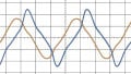
Figure 8. Comparison of the test results at different measuring voltages
Test specimen: Reactor with laminated core 3 UI 48
Measuring current: 10A
Curve 1: Measuring voltage 31V, pulse width 5000µs
Curve 2: Measuring voltage 270V, pulse width 500µs
Curve 3: Measuring voltage 400V, pulse width 330µs
Image used courtesy of Bodo’s Power Systems
The measuring voltage should therefore always be selected roughly as high as the voltage at the inductor in the real application. If the measuring voltage is chosen too large (i.e. the pulse width too small) or too small (i.e. the pulse width too large), the measurement result may deviate more or less, depending on the core material. The difference may possibly be small even if the measuring voltage is doubled, e.g. with ferrite cores. With other core materials, however, the difference can be quite significant, as shown in figure 8.
An automatic selection of the measurement parameters, as sometimes offered by competitors, is therefore absolutely nonsensical! No algorithm in the world can determine the voltage across the inductor in the real application. This feature only serves to conceal the meter's weaknesses such as insufficient sampling rate and memory depth by setting the measuring voltage in such a way that these limitations are hidden.
Sampling rate and pulse width range
The requirement that the measuring pulse should have the same pulse width as in the real application necessitates a very high sampling rate and a very wide pulse width range. This can be illustrated by 2 examples.
Example 1: A storage choke with a ferrite core for a switch mode power supply with a switching frequency of 200 kHz. This necessitates a pulse width of a few µs. Assuming a pulse width of 3 µs and requiring at least 150 sampling points for the inductance curve, this results in a sampling rate of at least 50 MS/s.
Example 2: A choke for railway applications is operated with a frequency of 16 2/3 Hz. The pulse width should therefore be about 30 ms (full-wave 60 ms, a half-wave 30 ms).
A high sampling rate and large pulse widths, however, lead to another problem. Either a disproportionately large memory depth is needed or a memory overflow occurs.
The Power Choke Tester DPG10/20 series, therefore, uses a specially developed A/D converter that has a special feature. The high sampling rate of 2 x 50 MS/s can be automatically reduced for long pulses so that the maximum possible pulse width is almost unlimited.
The pulse width can be set to between 3 µs and 70 ms, and could even be increased to several seconds if required. The Power Choke Tester DPG10/20 series is thus suitable for all core materials from several 100 kHz down to < 5 Hz.
Foresight
The second part of this series of articles describes the other methods for measuring inductance. These include small-signal measurement with sinusoidal voltages and currents with or without DC bias (LCR meter) and conventional measurement with mains voltage and mains current. The pulse measurement principle with SCR (which can’t be turned off ) propagated of late is also explained. It will show what considerable principle-related disadvantages all three measuring methods have compared to the pulse measuring method of the Power Choke Tester DPG10/20 series.
About the author
Dipl.-Ing. Hubert Kreis is the owner of ed-k. He studied electrical engineering at the Technical University of Stuttgart and since 1994 has worked for various companies in the development of switch mode power supplies, electrical drive systems for heavy vehicles, and power electronics for aviation equipment.
In 2002 he founded ed-k that specializes in inductance meters using the pulse measuring method with extremely compact IGBT high-power output stages and has helped this measuring principle to achieve a breakthrough worldwide.
This article originally appeared in Bodo’s Power Systems magazine.