Facebook
 Google
 GitHub
 Linkedin
GaN Transistors Simplify High-Current Motor Drive Inverter Design
Battery-powered industrial vehicles such as forklifts, manual handlers, or warehouse automatic vehicles require high-current inverters to drive the electric motors. Gallium nitride technology helps to increase the power capability and simplify the inverter design in these applications.
This article is published by EE Power as part of an exclusive digital content partnership with Bodo’s Power Systems.
An inverter for forklift applications is powered with a DC voltage between 24 V and 120 V and can source up to 900 ARMS motor phase current. Generally, each producer has a platform approach and sells product families divided by voltage range, where the inverters are sized on the maximum current that can be achieved for a transient period (e.g., 2 minutes).
![]()
Image used courtesy of Freepik
A typical inverter for these applications is contained in an IP65-rated enclosure (example: 150 mm x 120 mm x 60 mm) with a thick aluminum baseplate. Inside the enclosure, the power transistors are soldered to an insulated metal substrate (IMS) board thermally and mechanically connected to the aluminum baseplate. Above the IMS board is a super-dense PCB with gate drivers, analog signal conditioning, power supplies, and at least two microprocessors, one dedicated to functionality and the other to safety. A certain number of transistors in parallel is required to process the current and the heat generated by the conduction and switching dissipation.
Currently, silicon MOS technology dominates the market, imposing constraints on the maximum number of devices that can be used in parallel, the maximum PWM switching frequency, and the dead time between complementary switches. The first constraint limits the maximum current, while the other two degrade motor efficiency. With GaN technology, the scenario is now evolving.
GaN Advantage
The critical field in a semiconductor material determines the breakdown voltage of a device. For a given breakdown voltage, the higher the electric field, the shorter the width of the drift region. In a GaN transistor, the critical field is an order of magnitude higher than silicon, and the electron mobility due to the two-dimensional electron gas (2DEG) makes the ON resistance low while keeping its dimensions small.
The GaN technology is planar; for a given ON resistance, the devices have capacitances approximately an order of magnitude lower than their silicon counterparts. Smaller dimensions and capacitances allow more devices in parallel on the same substrate to process more current. Moreover, smaller capacitances help increase PWM frequency and reduce dead time to improve motor efficiency.
Simplified Layout for GaN Transistors in Motor Drive Applications
GaN transistors switch faster than equivalent Si MOSFETs. But with great power comes great responsibility: the layout must be carefully designed. The drain-source power loop circuits and the gate-source loop circuits are sensitive to parasitic inductances. This is important in power converters that must switch above 200 kHz. Motor drive GaN inverters switch up to 100 kHz, and the switching dv/dt is set to less than 10 V/ns to be compatible with motor winding insulation high-frequency breakdown requirements. While most layout considerations still hold, others can be relaxed without compromising the final outcome.
GaN FET Fundamental Layout Guidelines
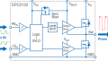
Reducing the parasitic inductances and following a symmetric approach is essential without compromising the modularity. Three types of parasitic inductance adversely affect the inverter operation, as shown in Figure 1:
- Common source parasitic inductance (CSI) (Figure 1 green boxes): The return path of the gate signal of a GaNFET must be separated from the high current path in the source pads. This parasitic inductance has the greatest detrimental effect on the converter operation and is the most frequent error encountered in design reviews. EPC GaN FETs do not have a dedicated Kelvin gate return connection, so this connection must be made in the PCB layout [1].
- Power loop parasitic inductance (LLoop) (Figure 1 brown boxes): The high-frequency current loop encompassing DC+ and GND must have low inductance to reduce ringing, which contributes to losses and associated EMI generation. The internal-vertical layout with the GND plane has been demonstrated to yield the lowest inductance layout [3].
- Gate loop parasitic inductance (LGate) (figure 1 magenta boxes): The recommended and the maximum voltage ratings for the gate of a GaN FET are more stringent than for Si MOSFETs; hence, particular care must be taken with the gate signals path that must always be paired with the gate return. This is the second most frequent error encountered in design reviews. When paralleling FETs, all gate paths should have the same impedance (i.e., the same length) to match voltage magnitude and propagation at each gate.
![]()
Figure 1. Parasitic inductances: (1) CSI, (2) Power loop, (3) Gate loop. Image used courtesy of Bodo’s Power Systems [PDF]
![]()
Figure 2. Paralleling a) transistors vs. b) half-bridges. Image used courtesy of Bodo’s Power Systems [PDF]
One consequence of these rules is that, for high-frequency GaN converters, it is common to parallel the half bridges instead of paralleling the transistors. An example is shown in Figure 2. However, a simpler approach has been adopted and demonstrated with the EPC9186 reference design, given that a motor drive switches slower than a high-frequency converter.
EPC9186 Layout Approach
EPC has released several reference design boards for motor drive inverters using GaN FETs and GaN integrated circuits. All reference design boards share the same block diagram and controller connector to help the designer scale up the current and voltage during the design phase of an inverter family.
The new EPC9186 measures 10 cm x 13.5 cm and is the power section of a motor drive inverter rated at 100 V and 150 ARMS steady state phase current. It comprises a 10-layer, 2-oz FR4 PCB and auxiliary power supplies to generate 5 V and 3.3 V from the DC Bus, phase voltage, current sensing circuits, and over-current protection comparators. The EPC9186 motor drive inverter can be paired with an EPC9147x controller, allowing the designer to use their preferred motion controller.
The EPC9186 switching cell has four EPC2302 transistors connected in parallel, placed with a simplified layout that relaxes the paralleling GaN FET design rules. The gate driver is on the left side of the switching cell; the low-side and high-side GaN FETs are placed in two rows toward the phase output connector.
Figure 3 shows the EPC9186 board and the switching cell details, where L1 and H1 are the low-side and high-side transistors nearest the gate driver, and L4 and H4 are the transistors farthest from the gate driver. The motor phase output connector is shown in the same figure.
![]()
Figure 3. EPC9186 100 V, 150 ARMS per phase motor drive board. Switching cell details on the right. Image used courtesy of Bodo’s Power Systems [PDF]
This layout partially follows internal vertical layout rule b) given in the previous section; that is, the first inner layer is a GND connection to minimize the power loop inductance, however, the switching cell has no high-frequency capacitors because the switching dv/ dt is low. The common guideline of having the same length for all gate signals is not strictly followed in the EPC9186 because the gate path length increases with the distance from the gate driver. The gate signals are encapsulated within two layers of the corresponding gate signal return that act as a shield. These two layers are connected to a single Kelvin point per transistor to reduce the common source inductance.
EPC9186 Experimental Results
Experimental tests showed that the simplified switching cell power section layout approach does not harm inverter performance. Figure 4 shows clean gate signals in all transistors, independently of the distance from the gate driver. Figure 5 shows the steady-state phase current capability as a function of the accepted temperature rise. The steady-state current depends on the thermal condition, and the board was tested using a heatsink cooled by 400 LFM airflow.
![]()
Figure 4. Gate signals H1-L1 vs. H4-L4 at +100 A and −80 A motor phase current. Time 50 ns/div. Image used courtesy of Bodo’s Power Systems [PDF]
![]()
Figure 5. EPC9186 current vs. delta temperature and frequency. Image used courtesy of Bodo’s Power Systems [PDF]
Conclusion
EPC GaN FET devices are smaller than silicon MOSFETs and have lower thermal resistance to the case, allowing double-side cooling. They allow more devices to be connected in parallel that can conduct more current in the same inverter enclosure volume while showing superior thermal management. This benefits battery-powered industrial vehicles such as forklifts, manual handlers, or warehouse automatic vehicles demanding higher currents in smaller volumes.
References
[1] A. Lidow, M. De Rooij, J. Strydom, D. Reusch, J. Glaser, GaN Transistors for Efficient Power Conversion. Third Edition, Wiley. ISBN 978-1-119-59414-7
[2] A. Lidow, GaN Power Devices and Applications. Chapter 6, First Edition, Power Conversion Publications. ISBN 978-0-9966492-2-3
[3] D. Reusch and J. Strydom, “Understanding the effect of PCB layout on circuit performance in a high-frequency gallium nitride-based point of load converter,” 2013 Twenty-Eighth Annual IEEE Applied Power Electronics Conference and Exposition (APEC), Long Beach, CA, USA, 2013, pp. 649-655, doi: 10.1109/ APEC.2013.6520279.
[4] https://epc-co.com/epc/products/gan-fets-and-ics/epc2302
[5] https://epc-co.com/epc/products/demo-boards/epc9186
[6] https://epc-co.com/epc/products/demo-boards/epc9147c
[7] https://epc-co.com/epc/markets-and-applications/industrial/motor-drive
[8] https://www.atech-antriebstechnik.de/en/motiontechnology/zapi-inverters-controller-l-motor-controller-steering-systems
This article originally appeared in Bodo’s Power Systems [PDF] magazine.