Facebook
 Google
 GitHub
 Linkedin
National Electrical Code Basics: Feeder and Branch-circuit Load Calculations
Learn about load computations in three-phase and single-phase feeders and branch circuits.
All electrical work, from design to commissioning, requires calculations. Anyone involved in any phase of electrical work, regardless of size, will frequently need to use some math. Measures are different for residential, commercial, and industrial occupancies. This article reviews some calculations regarding feeder and branch circuit characteristics and loading.
Image used courtesy of Pixabay
Branch-circuit Conductors
Example 1. Figure 1 shows two 3-phase, 4-wire branch circuits supplying 120 V incandescent lighting balanced loads for more than 3 hours. The conductor size contemplates the voltage drop. The ambient temperature is not higher than 30°C. Terminations 60°C.
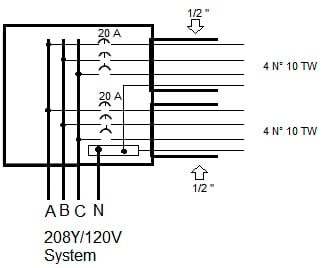
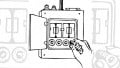
Figure 1. Two lighting branch circuits. Image used courtesy of Lorenzo Mari
a. What’s the branch-circuit ampere rating?
According to Section 210.18, the maximum permissible ampere rating or setting of the overcurrent protective device establishes the branch-circuit rating. Then, the rating is 20 A.
b. What’s the conductor ampacity?
Table 310.16 shows an ampacity of 30 A for N° 10, TW, conductors under the 60°C column. Loads are balanced, and the current in the neutral is 0 A. There are no more than three current-carrying conductors in the conduits – no adjustment required – and ambient temperature is not higher than 30°C – no correction needed. See 310.15(B)(1) and 310.15(C)(1).
c. What’s the maximum permissible load in each circuit?
According to Section 210.20(A), the rating of the overcurrent device shall not be less than 125% of the continuous load. Then, 20 A = 1.25 x maximum permissible load. Maximum permissible load = 20 A/1.25 = 0.8 x 20 = 16 A.
d. What’s the maximum permissible load using a ¾” conduit? The maximum permitted load does not depend on the conduit size. It is 16 A.
Example 2. Placing the eight conductors of the previous example in one conduit.
a. What size of rigid metal conduit (RMC) is required? Table C.9 shows that ¾” may contain up to 9 N° 10 AWG TW conductors.
b. What’s the branch-circuit ampere rating? The rating is 20 A.
c. What’s the conductor ampacity? There are six current-carrying conductors in one conduit. Table 310.15(C)(1) shows an 80% adjustment factor. Ampacity = 0.8 x 30 = 24 A.
d. What’s the maximum permissible load in each circuit? 16 A, as in the previous example.
Example 3. A 120 V system supplies power to 215 fluorescent lighting fixtures in a department store for more than 3 hours. Each lighting unit takes 2.2 A. How many 20 A branch circuits will feed the fixtures?
According to 210.20(A), the rating of the overcurrent device shall not be less than 125% of the continuous load.
215 x 2.2 A x 1.25 = 591.25 A. 591.25 A/20 A = 29.56. The system requires 30 20 A branch circuits.
Example 4. In the previous example, what’s the total real power of the lighting load if the power factor is 0.8?
P = V x I x PF = 120 V x 215 x 2.2 A x 0.8 = 45.4 kW
2- and 3-wire Branch Circuits
Example 5. Figure 2 shows a 120/240 V 3-wire single-phase panelboard supplying household appliances.

Figure 2. 2- and 3-wire branch circuits. Image used courtesy of Lorenzo Mari
a. Find the current consumed by the coffee maker.
I = P/V = 1 440 W/120 V = 12 A.
b. Find the current consumed by the mixer and toaster.
Total load = 600 W + 1200 W = 1 800 W.
I = P/V = 1 800 W/120 V = 15 A.
c. Find the feeder currents when supplying power only to a and b above.
Phase A supplies 12 A to the coffee maker.
Phase B supplies 15 A to the mixer and toaster.
The neutral carries the unbalance of the loads = 15 A – 12 A = 3 A.
d. Find the feeder currents when supplying power only to fans and grille.
Fan 1 takes 120 W/120 V = 1 A from phase B.
Fan 2 takes 120 W/120 V = 1 A from phase A.
The grille takes 1 200 W/240 V = 5 A from phases A and B.
Total current in phase A = 1 A + 5 A = 6 A.
Total current in phase B = 1 A + 5 A = 6 A.
The grill does not contribute to the neutral current because it is a phase-to-phase load. Both fans take 1 A in different phases, and the unbalance of the load is 1 A – 1 A = 0 A. Then, the neutral current is 0 A.
e. Find the neutral current in d above, turning off the fan 2.
Only fan 1 contributes to the neutral. Then, the neutral carries 1 A.
f. Find the feeder currents when turning on all loads.
Total current in phase A = 12 A + 1 A + 5 A = 18 A.
Total current in phase B = 15 A + 1 A + 5 A = 21 A.
The neutral carries the unbalance of the load = 21 A – 18 A = 3 A.
As aforesaid, the grill does not contribute to the neutral current because it is a phase-to-phase load. Then, remove the 5 A from the calculations. 16 A – 13 A = 3 A.
g. Find the maximum unbalanced load the feeder will carry.
Section 220.61(A) states that the maximum unbalanced load shall be the maximum net calculated load between the neutral conductor and an ungrounded conductor.
All loads, but the grill, are connected between the neutral and ungrounded conductors. The neutral in figure 2 is the grounded conductor.
Phase A to neutral load = 12 A + 1 A = 13 A.
Phase B to neutral load = 15 A + 1 A = 16 A.
The maximum unbalanced load is 16 A.
h. Find the minimum conductor size for the branch circuits.
The maximum current carried in a branch circuit is 15 A (mixer and toaster). Table 310.16 shows an ampacity of 15 A for a conductor size N° 14 AWG TW. Yet, Section 210.19(A)(2) states that the conductors cannot have an ampacity below the branch circuit rating.
Section 210.18 affirms that the branch circuits shall be rated per the maximum permitted ampere rating or setting of the overcurrent device. Figure 2 shows 20 A circuit breakers. Therefore, these 20 A branch circuits require a minimum conductor ampacity of 20 A, corresponding to size N° 12 AWG TW.
Load in Dwelling Units
Example 6. An apartment complex (multifamily dwelling) consists of 20 apartments (dwellings units) with a floor area of 80 m² each (calculated according to Section 220.11). Each apartment has an 11 kW electric range. The power supply is 120/240V, 3-wire, single-phase. What is the total lighting and appliance load for each apartment?
Section 220.14(J) requires a minimum unit load of 33 VA/m² for lighting and general-purpose receptacles (lamps, radios, TV, vacuum cleaner, etc.).
80 m² x 33 = 2 640 VA.
Section 210.11(C)(1) requires a minimum of two 20 A small-appliance branch circuits (portable appliances such as toasters, coffee makers, and irons in kitchen, pantry, dinning-room, etc.). Section 220.52(A) requires 1 500 VA per branch circuit.
1 500 VA x 2 = 3 000 VA.
Section 210.11(C)(2) requires a minimum of one 20 A branch circuit for the laundry area. Section 220.52(A) requires not less than 1 500 VA per branch circuit.
1 500 VA x 1 = 1 500 VA.
Demand factors contemplate that not all circuits in the apartment work at their maximum capacity simultaneously.
Sections 220.52(A) and 220.52(B) permit adding the small-appliance and laundry loads to the general lighting load and subjecting them to the demand factors in Table 220.42.
For dwelling units, Table 220.42 shows a 100 % demand factor for the first 3 000 VA and 35% from 3 001 VA to 120 000 VA.
Ranges are multiunit loads assembled as a single appliance. The load rating of a range is the total of the oven load plus all burners on their highest setting. It is unlikely to have all these heating elements in use altogether. Column C of Table 220.55 shows a maximum demand of 8 kW for one 11 kW range.
Section 220.55 considers kW and kVA equivalent for loads calculated under this section.
Table 1 summarizes the load calculations (assuming all loads with the same power factor).
| Topic | Gross computed load (VA) | Demand factor (%) | Net computed load (VA) |
| Lighting and general purpose receptacles |
2 640 |
||
|
Small appliance circuits |
3 000 |
||
|
Laundry circuit |
1 500 |
||
|
Total gross computed load |
7 140 |
||
|
First 3 000 VA |
100 |
3 000 |
|
|
Remaining 4 140 VA |
35 |
1 449 |
|
|
Range |
11 000 |
Table 220.55 |
8 000 |
|
Net computed load |
12 449 |
Table 1. The total lighting and appliance load for each apartment is 12 449 VA.
Electric Cooking Appliances in Dwelling Units
Example 7. Compute the minimum branch-circuit rating to supply power to a 16.6 kW 120/240 V household range (See figure 3).
Column C of Table 220.55 applies to ranges, not over 12 kW rating. Note 1 of the table indicates that for higher ratings, but no more than 27 kW, the maximum demand in column C must be increased by 5% for each additional kW of rating or major fraction above 12 kW.
Additional kW of rating = 16.6 kW – 12 kW = 4.6 kW.
Demand in column C for one range = 8 kW.
5% of demand in column C = 0.05 x 8 kW = 0.4 kW.
Number of times to increase demand = 4.6. Say five times.
Increase of demand = 5 x 0.4 kW = 2 kW.
Maximum demand = 8 kW + 2 kW = 10 kW.
Another method:
Increasing 5% for each additional kW is equivalent to
5 x 5% = 25%.
8 kW is 100%.
(100% + 25%) x 8 kW = 125% x 8 kW = 1.25 x 8 kW = 10 kW.
Current in branch circuit = 10 kW/240 V = 41.67 A. Say 42 A.
Minimum branch-circuit rating = 50 A (see Section 210.23(C).
Minimum conductor size = N° 6 AWG TW (See Table 310.16).
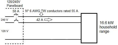
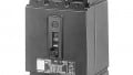
Figure 3. Branch circuit for an electric cooking appliance. Image used courtesy of Lorenzo Mari
Example 8. Compute the minimum branch-circuit rating to supply power to two 6 kW wall-mounted ovens and one counter-mounted cooking unit in the same room. Power ratings from nameplates (See figure 4).
Note 4 of Table 220.55 allows to add the nameplate ratings of the individual appliances and proceed as a single range.
Total rating = 3 x 6 kW = 18 kW.
From here, let’s continue as in example 7 above.
Additional kW of rating = 18 kW – 12 kW = 6 kW.
Demand in column C for one range = 8 kW.
5% of demand in column C = 0.05 x 8 kW = 0.4 kW.
Number of times to increase demand = 6.
Increase of demand = 6 x 0.4 kW = 2.4 kW.
Maximum demand = 8 kW + 2.4 kW = 10.4 kW.
Another method:
Increasing 5% for each additional kW is equivalent to
6 x 5% = 30%.
8 kW is 100%.
(100% + 30%) x 8 kW = 130% x 8 kW = 1.30 x 8 kW = 10.4 kW.
Current in branch circuit = 10.4 kW/240 V = 43.33 A. Say 44 A.
Minimum branch-circuit rating = 50 A (see Section 210.23(C).
Minimum conductor size = N° 6 AWG TW (See Table 310.16).
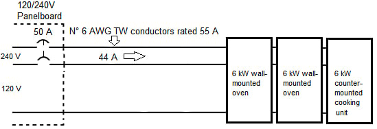
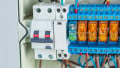
Figure 4. Branch circuit for electric cooking appliances. Image used courtesy of Lorenzo Mari
Conclusion
Electrical calculations are fundamental in electrical work. This article gives examples of calculations related to feeders and branch circuits complying with National Electrical Code® rules.
Although sound, accurate, realistic, and practical calculations are the foundation of economics in the design and installation of all electrical work, the NEC® purpose is safety, not convenience or adequacy.
The NEC® states minimum requirements. The electrical people are responsible for determining the sizes, ratings, dimensions, and other quantitative characteristics of equipment, material, and labor to assure the best and safest work.