Facebook
 Google
 GitHub
 Linkedin
National Electrical Code 2023 Basics: Grounding and Bonding Part 15
Learn about the rules for bonding services and communication systems.
Bonding is connecting metallic components to ensure the electrical continuity needed to return the ground-fault current to its source. Part V of NEC’s Article 250 states the rules for bonding services, communication systems, other enclosures, hazardous (classified) locations, piping systems, exposed structural metal, and lightning protection systems.

Image used courtesy of Pixabay
National Electrical Code Section 250.90 General Requirement for Bonding
The NEC defines bonding as a connection to establish electrical continuity and conductivity. Section 250.90 requires bonding when needed to conduct ground-fault currents–the conductor size must be capable of handling such currents.
National Electrical Code Section 250.92 Bonding of Services
Section 250.92(A) Bonding of Equipment
Bond the normally non-current-carrying metal parts of the following equipment:
- Service raceways, cable trays, cablebus framework, auxiliary gutters, or service cable armor or sheath, containing, enclosing, or supporting service conductors, except as permitted in Section 250.80.
Section 250.80 requires the connection of metal service enclosures and raceways to the grounded conductor in grounded systems and the grounding electrode conductor in ungrounded systems. The Exception to this section deals with the metal components in a run of underground nonmetallic raceways isolated from possible contact by a cover of not less than 0.45 m.
- All service conductors enclosures involving meter fittings, boxes, or the like inserted in the service raceway.
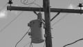
Typically, utility-supply secondary conductors run to the service overcurrent protective device located near the point of entry to the building. The protection stays on the primary side of the utility transformer, usually placed far from the building. The service overcurrent protective device does not correctly protects the utility-supply secondary conductors from short circuits or ground faults.
Grounding and bonding all the enclosures containing the service conductors help to provide enough fault current to clear shorts or ground faults on the supply side of the service overcurrent protective device.
Figure 1 shows how bonding ensures a continuous, low-impedance path for ground-fault current through service conductor enclosures.

Figure 1. A low-impedance path for ground-fault current. Image used courtesy of Lorenzo Mari
Section 230.43 lists the wiring methods permitted to enclose service-entrance conductors.
Section 250.92(B) Method of Bonding
The high level of ground-fault current obtainable on the line side of the service equipment requires a proper path for returning to the source. For this reason, the bonding constraints are more limiting at services than downstream from the service.
Installing bonding jumpers around weakened connections, such as reducing washers or oversized, concentric, or eccentric knockouts, is mandatory on the line side of the service disconnecting means.
The knockouts’ outer rings are unsuitable for service-conduit bonding as they weaken the current flow through the reduced metal cross-section. Size the bonding jumpers per Section 250.102(C).
Standard locknuts or bushings are suitable for the mechanical connections of the raceways. Yet, they are not permitted as the only bonding means. A typical practice is placing standard locknuts outside the enclosure on a conduit with bonding bushing inside.
Figure 2 shows a listed box equipped with concentric or eccentric knockouts.

Figure 2. Concentric or eccentric knockouts. Image used courtesy of Lorenzo Mari
Ensure the electrical continuity using supply-side bonding jumpers when employing concentric, eccentric, or oversized knockouts. These bonding jumpers connect raceways to enclosures.
Ensure the electrical continuity in one or more of the following ways:
- Bonding equipment to the grounded service conductor with a method specified in Section 250.8(A).
Section 250.8(A) lists the eight permitted methods to connect equipment grounding conductors, grounding electrode conductors, and bonding jumpers. Section 250.8(B) prohibits using connection devices or fittings depending only on solder.
Figure 3 shows a grounding and bonding assembly for a service with one disconnecting means.

Figure 3. Grounding and bonding with one disconnecting means. Image used courtesy of Lorenzo Mari
Figure 4 shows a grounding and bonding assembly for a service with various disconnecting means.

Figure 4. Grounding and bonding with several disconnecting means. Image used courtesy of Lorenzo Mari
- Connections made up wrenchtight employing threaded couplings, threaded entries, or listed threaded hubs on enclosures.
The market offers many products, allowing designers and installers to choose different methods.
Figure 5 shows a grounding and bonding threaded hub, and Figure 6 a few threaded couplings.

Figure 5. Grounding and bonding threaded hub. Image used courtesy of Bridgeport

Figure 6. Threaded couplings. Image used courtesy of ABB
Threadless couplings and connectors where made up tight for metal raceways and metal-clad cables.
Figure 7 shows an insulated threadless bushing for grounding, and Figure 8 a threadless raintight coupling.

Figure 7. Threadless bushing for grounding. Image used courtesy of Bridgeport

Figure 8. Threadless raintight coupling. Image used courtesy of Bridgeport
Other listed devices, such as bonding-type locknuts, bushings, or bushings with bonding jumpers – no standard locknuts and bushings.
Figure 9 shows a bonding-type locknut, Figure 10 a bonding-type bushing, and Figure 11 a grounding-type wedge lug.

Figure 9. Bonding-type locknut. Image used courtesy of Bridgeport

Figure 10. Bonding-type bushing. Image used courtesy of Bridgeport
Bonding bushings and locknuts have setscrews that bite either the conduit or the metal of the cabinet, preventing the bushing or locknut from turning and ensuring good electrical continuity.
The connector on the side of the bushing allows the connection of a bonding jumper to the grounded conductor busbar (maybe the neutral).

Figure 11. Grounding-type wedge lug. Image used courtesy of ABB
When using EMT, you may install a grounding wedge on the inside of the cabinet, between the cabinet’s wall and the connector’s locknut.
National Electrical Code Section 250.94 Bonding for Communication Systems
Connect the bonding conductor terminations per 250.94(A) or (B).
Section 250.94(A) The Intersystem Bonding Termination (IBT) Device
Intersystem means bonding the electrical system and other systems such as communications, radio and TV equipment, and broadband communication systems to reduce their potential differences. One source of induced potential differences is lightning strikes.
Provide an IBT for connecting intersystem bonding conductors external to the enclosures, at the service equipment or metering equipment enclosure, and the disconnecting means for any other building or structure supplied by a feeder or branch circuit.
Figure 12 shows an aluminum intersystem bonding termination ground bar.

Figure 12. Intersystem bonding termination. Image used courtesy of ABB
An IBT must comply with the following:
- Be accessible.
- Have the capacity to connect three or more intersystem bonding conductors.
- Do not interfere with opening a service enclosure, a building or structure disconnecting means, or the metering equipment.
- Be securely mounted
◦ At the service equipment, mount and connect the IBT to a metal enclosure for the service equipment, to a metal meter enclosure, or to an exposed nonflexible metal service raceway. Or connect it to the metal enclosure for the grounding electrode conductor with a copper conductor size N° 6 AWG as a minimum.
◦ At a building or structure, disconnecting means, where supplied by a feeder or branch circuit, connect the IBT to the metal enclosure of the disconnecting means. Or connect it to the metal enclosure for the grounding electrode conductor with a copper conductor size N° 6 AWG as a minimum.
- Be listed as grounding and bonding equipment.
Figure 13 shows the grounding electrode systems of a typical home CATV installation and a service panel bonded together through intersystem bonding. In this way, no potential differences between the two grounding systems exist.

Figure 13. Bonding CATV and service panel grounding electrode systems. Image used courtesy of Lorenzo Mari
250.94(B) Other Means
Connecting the terminations to a copper or aluminum busbar of standard dimensions is permitted. The busbar length must accommodate at least three terminations for communication systems, not counting other connections.
Figure 14 shows copper and aluminum grounding busbars.

Figure 14. Grounding busbars. Image used courtesy of nvent/ERICO
To size the conductor connecting the busbar to the grounding electrode system, choose the largest of the following:
1. The largest grounding electrode conductor connected to the busbar.
2. As required or permitted in Section 250.94(A) above.
According to the Exception to sections 250.94(A) and (B), there is no need to provide means for connecting intersystem bonding conductors in buildings or structures without communication systems.
Takeaways of Bonding Services and Communication Systems
- Bonding the enclosures containing service conductors ensures electrical continuity for the ground-fault current.
- The market offers products that allow designers and installers to choose among the different bonding methods outlined in the NEC.
- Bonding the grounding systems of different communications systems reduces damages from induced potential differences between them.
- The device implementing the connection between communication grounding systems is the Intersystem Bonding Termination.
To catch up on Lorenzo Mari’s series on National Electrical Code 2023 Basics: Grounding and Bonding, follow these links:
- National Electrical Code 2023 Basics: Grounding and Bonding Part 1
- National Electrical Code 2023 Basics: Grounding and Bonding Part 2
- National Electrical Code 2023 Basics: Grounding and Bonding Part 3
- National Electrical Code 2023 Basics: Grounding and Bonding Part 4
- National Electrical Code 2023 Basics: Grounding and Bonding Part 5
- National Electrical Code 2023 Basics: Grounding and Bonding Part 6
- National Electrical Code 2023 Basics: Grounding and Bonding Part 7
- National Electrical Code 2023 Basics: Grounding and Bonding Part 8
- National Electrical Code 2023 Basics: Grounding and Bonding Part 9
- National Electrical Code 2023 Basics: Grounding and Bonding Part 10
- National Electrical Code 2023 Basics: Grounding and Bonding Part 11
- National Electrical Code 2023 Basics: Grounding and Bonding Part 12
- National Electrical Code 2023 Basics: Grounding and Bonding Part 13
- National Electrical Code 2023 Basics: Grounding and Bonding Part 14