Facebook
 Google
 GitHub
 Linkedin
Analyzing the Inner Workings of a Variable Frequency Drive’s Inverters
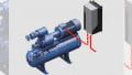
This teardown looks at the inner workings of the Hitachi SJ P1 Variable Frequency Drive, an inverter for industrial applications and part of a line of industrial inverters.
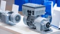
The SJ-P1 inverter can be used to drive both induction motors and permanent magnet motors. While induction motors are more commonly found in motor-driven systems, they are often larger in size and less efficient than permanent magnet motor solutions. While permanent magnet motor solutions tend to have a higher initial cost, they may offer a smaller size for more compact mechanical packages and higher efficiency. Although the permanent magnet motor offers many benefits, there is a problem of permanent magnet demagnetization when the inverter is overloaded over time. The SJ-P1’s over-current trip feature uses many isolated current detection and protection components to prevent the inverter from overloading and suppresses the demagnetization of permanent magnet motors.
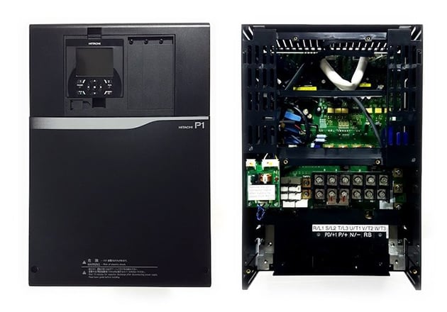
Figure 1: The Hitachi SJ Series P1 variable frequency drive.
The SJ-P1 Series is designed for easy integration with various networks using optional Fieldbus modules like RS485-Modbus (built-in), RS422 port (built-in), Ethernet, EtherCAT, ProfiNET and Profibus-DP. The SJ-P1 inverter is used in a wide variety of applications including industrial fans, hydraulic pumps, cranes and lifts used in warehouse automation and injection molding machines. Now, let's take a look at the inner workings of this piece of equipment.
General Specifications
-
Model and Ratings: SJ-P1, 15kW, 35A, 3-phase 400V class
-
Sine-wave PWM system
-
0.00 to 590.00 Hz output frequency range
-
Protection functions: Overcurrent error, overload error, brake resistor overload, overvoltage error, memory error, undervoltage error, current detector, etc.
External and Enclosure
-
Dimensions: 390mm x 245mm x 190mm
-
Weight: 16kg
-
Operating ambient temperature: -10° to 40°C
-
Installation class: A maximum altitude of 1000m, without gases or dust
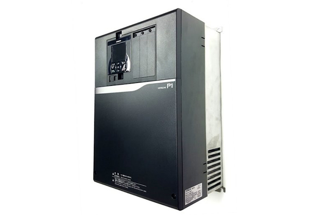
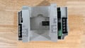
Figure 2: The Hitachi SJ Series P1 enclosure.
DC Bus Capacitor
- DC Bus Bulk Capacitor: Nippon Chemi-con (2pcs) 400V/4400µF electrolytic capacitors.
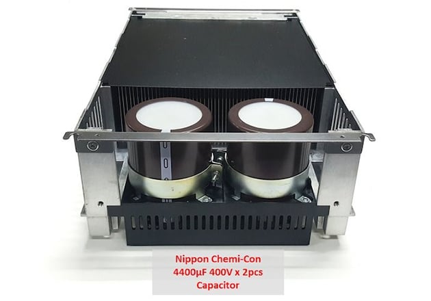
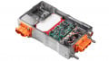
Figure 3: The DC bus capacitor
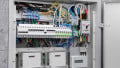
Main Controller Board
-
PWM MCU: Renesas R5F571MFCDFC industrial equipment-specific real-time engine. A 32-bit microcontroller capable of operation up to 240 MHz.
-
Programmable Logic Device: Altera EPM240T100I5N. The MAX® II family of instant-on, non-volatile CPLDs with densities from 240 to 2,210 logic elements (LEs) and non-volatile storage of 8Kbits.
-
Isolation: Toshiba
-
TLP2362 (4pcs) 10Mbd high-speed photocoupler
-
TLP2301 (4pcs) 20 kbps photo-transistor with high-speed detector.
-
TLP291 photo-transistor.
-
TLP290 (4Pcs) photo-transistor with AC inputs.
-
-
Relay: Panasonic JQ1-5V-F general purpose relays 5A, 5VDC, 400mW SPDT (1 Form C).
-
Relay: Fujitsu FTR-F3AA012E general purpose relays, 12VDC, 200mW SPST (1 Form A).
-
Line input and three-phase output contactor board.
-
Current transducer: LEM HLSR 62-P (2pcs) open-loop 62A current transducer with galvanic separation.
-
Capacitor: Okaya LE 105 310V 1µF film capacitor.
-
Resistor: Iwaki 3.3/6.6ΩJ (8pcs) resistor.
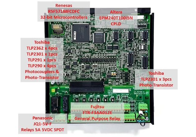
Figure 4: The main controller board
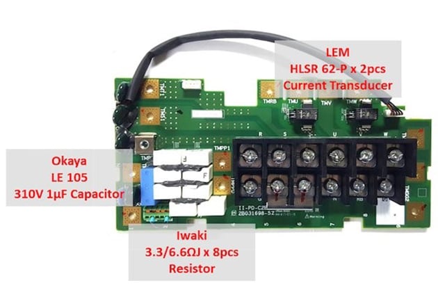
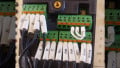
Figure 5: Line input and three-phase output contactor board.
Line Input and 3-Phase Output Contactor Board
-
Current Transducer: LEM HLSR 62-P (2pcs) open-loop 62A current transducer with galvanic separation.
-
Capacitor: Okaya LE 105 310V 1µF film capacitor.
-
Resistor: Iwaki 3.3/6.6ΩJ (8pcs) resistor.
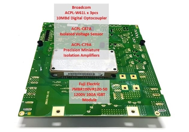
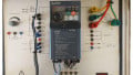
Figure 6: The power electronics board
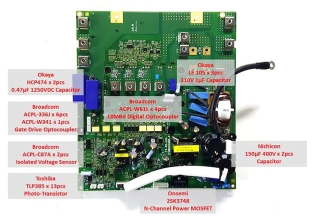
Figure 7: Another view of the power electronics board.
Power Electronics Board
-
IGBT: Fuji Electric 7MBR100VR120-50 1200V 100A IGBT module with rectifier, brake, inverter and thermistor stage.
-
Isolation: Broadcom (Avago Technologies)
-
ACPL-W61L (3pcs) ultra-low-power 10MBd digital CMOS optocoupler.
-
ACPL-C87A precision optically isolated voltage sensor with 0.5% high gain accuracy.
-
ACPL-C79A precision miniature isolation amplifier with 0.5% high gain accuracy.
-
-
Isolation: Broadcom (Avago Technologies)
-
ACPL-336J (6pcs) 2.5A IGBT gate drive optocoupler with integrated (VCE) desaturation detection, active Miller clamping, fault, and UVLO status feedback.
-
ACPL-W341 3A output current IGBT gate drive optocoupler with rail-to-rail output voltage.
-
ACPL-W61L (4pcs) ultra-low-power 10MBd digital CMOS optocoupler.
-
ACPL-C87A (2pcs) precision optically isolated voltage sensor with 0.5% high gain accuracy.
-
-
Isolation: Toshiba TLP385 (13pcs) photo-transistor with 5000Vrms in a 4-pin SO6L package.
-
Switching Power Supply: ON Semiconductor 2SK3748 N-channel 1500V 4A power MOSFET.
-
Capacitor: Nichicon (2pcs) 400V/150µF electrolytic capacitor. Capacitor: Okaya
-
LE 105 (3pcs) 310V 1µF film capacitor.
-
HCP474 (2pcs) 0.47µF 1250VDC capacitor
-
About the Author
Nilo Mitra is a freelance technical writer/editor specializing in writing on IT/software, Web/Internet and telecommunications topics, in which areas he has had 35+ years of professional experience. He is able to write on complex technical subjects in a way that makes these understandable to an educated, professional audience who are not necessarily subject matter experts.
This article originally appeared in the Bodo’s Power Systems magazine.