Facebook
 Google
 GitHub
 Linkedin
Motor Starters Part 7: Selecting and Sizing Variable Frequency Drives
Selecting and sizing a variable frequency drive (VFD) can be confusing, even for the most seasoned engineer. This article makes it easy.
To catch up on Simon Mugo’s series on Variable Frequency Drives, please visit:
Motor Starters Part 6: Variable Frequency Drives
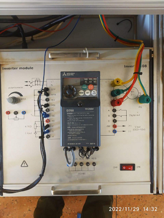
Figure 1. Mitsubishi VFD drive. Image used courtesy of Simon Mugo
The goal of a variable frequency drive (VFD) is to convert the input of a single-phase alternating current into direct power and then inverse the power into three-phase alternating current output. These important motor control drives are built for many power applications such as flow, pressure maintenance, oxygen dissolution, and level maintenance.
There are some basic things to know before addressing VFD selection and sizing. First, VFDs cannot generate torque or horsepower. Second, VFDs are intended to supply electric current with the correct frequency and voltage for attaining desired speeds for running a given motor.
Now, you are ready to learn how to select and size VFDs.
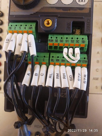
Figure 2. Mitsubishi VFD drive cable termination. Image used courtesy of Simon Mugo
Motor Selection
Before selecting and sizing VFDs, choose the correct motor and select the right VFD to drive the motor. The formula used in motor selection differs based on how the motor is operated. The motor can either be operated through vertical or horizontal movement.
Horizontal Movement
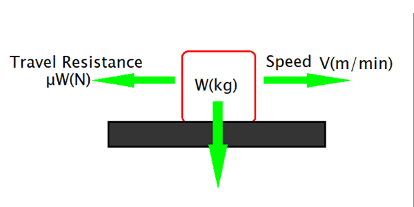
Figure 3. Horizontal movement. Image used courtesy of Simon Mugo
From the diagram, W (kg) is the traveling object’s total weight, V (m/min) is the speed, and μ is the system frequency factor.
Let p be the force power required to drive the motor. This is calculated using the formula
\[P=\frac{\mu WV}{6120\eta}\,where\,the\,units\,are\,in\,kW\]
Problem 1
The mass of an object is 80 kg, and its speed, frequency, and efficiency are 80 m/min, o.2, and 0.8, respectively. Calculate the motor driving force.
Solution 1
\[P=\frac{\mu WV}{6120\eta}\]
\[P=\frac{80\times0.2\times80}{6120\times0.8} = 0.26kW\]
Vertical Movement
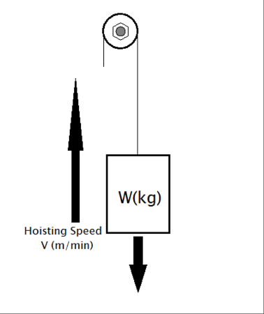
Figure 4. Vertical movement. Image used courtesy of Simon Mugo
If an object of mass W (kg) is subjected to a hoisting speed of V (m/min), then the force P required to drive the motor is determined using the formula
\[P=\frac{\mu WV}{6120\eta}\]
Where
\[\eta=Efficiency\,of\,the\,Motor\,System\]
Problem 2
The object has a mass of 50 kg and a hoisting speed of 60 m/min with an efficiency of 0.8. Calculate the force required to drive the motor for hoisting the load.
Solution 2
\[P=\frac{\mu WV}{6120\eta}\]
\[P=\frac{50\times60}{6120\times0.8}=0.61kW\]
Motor and VFD Sizing Considering Acceleration/Deceleration
For acceleration and deceleration, capacity size selection must be determined according to the machine movement. Check the machine data recorded on the nameplate, including the required operation pattern.
Below are the steps to follow during the selection process.
- Step 1: Calculate the machine load torque. This is the load torque that is significant in moving the load.
- Step 2: Calculate the moment of inertia of the power machine. The moment of inertia is represented by J. This is the value used to indicate how easy or difficult it is to stop or move an object. This can be compared to the loading on the back of an automotive track.
- Step 3: Find the pattern of operation of the machine. This is derived from the travel and stop time of the machine’s cycle operation.
Checking Figure 5 below, the area marked in gray and black strips represents the travel amount.
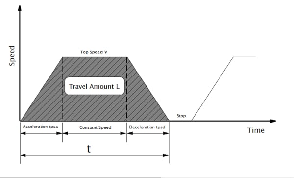
Figure 5. Travel amount graph. Image used courtesy of Simon Mugo
Given that top speed is V (mm/s), acceleration is tpsa(s), deceleration is tpsd(s), travel time is t(s), travel amount is L (mm), and tpsa is equal to tpsd, the following formula shows their relationship.
\[L=V(mm/s)\times(t-tpsa)mm\]
- Step 4: Tentatively carry out motor selection. Choose the motor that satisfies the moment of inertia J and the load torque. Remember that the rated torque of the motor must be higher than the load's torque. Otherwise, the motor could break down.
- Step 5: Compute the torque with the tentatively selected motor. The torque calculations are carried out by the following listed conditions:
❖ Torque needed to accelerate the motor to a constant operating speed from the start.
❖ Torque necessary for maintaining the load at a constant operating speed.
❖ Torque needed to decelerate the motor to a stop.
❖ The predicted heat generated by the motor.
By involving the values of motor currents obtained in Steps 1 through 3 and assuming the one-cycle period, compute an equivalent current using the formula below and compare the result with the rated current. The motor size should have an equivalent current less than its rated current.
\[Motor\,Equivalent\,Current-\sqrt{\frac{\sum(ln^{2}\times tn)}{\sum(Cn\times tn)}}\]
Where Cn is the cooling factor
- Step 6: Check the need for the brake resistor. The brake resistor is necessary for a regenerative brake. Carry out calculations on the braking power from the energy generated when using a regenerative brake during deceleration. Check if the computed power range is within the allowed performance range and specifications. If the power goes beyond the range, install a brake resistor externally.
Key Takeaways of Selecting and Sizing VFDs
- Variable frequency drives convert single-phase AC into DC before inverting it into three-phase AC output.
- Motors are operated through either horizontal or vertical driving forces.
- Horizontal movement driving force can be calculated using the formula
\[P=\frac{\mu WV}{6120\eta}\,where\,the\,units\,are\,in\,kW\]
- Vertical movement driving force can be computed by use of the formula listed below.
\[P=\frac{\mu WV}{6120\eta}\]
- Motor and VFD selection process can be carried out by following six important steps: Calculate the machine load torque, calculate the moment of inertia of the given machine, find the pattern of operation used in the machine, carry out motor selection, compute the torque of the selected motor, and check if brakes are required during deceleration.
- Computing the motor equivalent current can be achieved using the formula
\[Motor\,Equivalent\,Current-\sqrt{\frac{\sum(ln^{2}\times tn)}{\sum(Cn\times tn)}}\]
The next article in this series will address the causes of failures in Variable Frequency Drives.