Facebook
 Google
 GitHub
 Linkedin
Low-inductive three-level Modules for 1+ MW 1500 VDC Solar PV Central Inverters
This article highlights Vincotech GmbH the benefits of combining the lowinductiveVINco X12 package and the Mitsubishi gen 7 for outstanding efficiency.
With multi-string inverters gaining ground in the utility-scale PV market, new solutions for Central Inverters are needed. This article presents the benefits of combining the lowinductiveVINco X12 package and the new Mitsubishi gen 7, achieving an outstanding efficiency and power density to meet the highly demanding requirements of the solar PV inverter market.
Rising cost pressure is driving demand for solar energy systems rated beyond 1000 VDC. The industry has responded with standards and components enabling up to 1500 VDC. Multi-string inverters are evolving fast to adapt to these new requirements. The latest devices are able to handle 80+ kVA. This is why the price gap between multi-string and central inverters is closing and the competition between these solutions is heating up for utility-scale applications. With string inverters gaining market share in these application, engineers are hard-pressed to act fast and respond with innovative answers. Two-level solutions are no longer competitive; more advanced topologies are needed to stay in the game.
VINco X – the three-level package for central inverters
Simply adapting two-level housings to three-level topologies is certainly not the right answer. This would limit the maximum frequency and negate some of the advantages of NPC configurations. With this in mind, Vincotech tapped its deep well of experience with three-level modules to come up with high-power solutions. Low inductive VIN housings are built to handle higher switching frequencies, thereby enabling engineers to reduce overhead in passive components and achieve outstanding efficiencies.

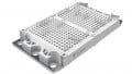
Figure 1: The VINcoNPC X12 diagrammed
The VINcoNPC X12 family meets the challenging requirements for central inverters, while retaining the string inverter’s speed and flexibility. The terminal connection allows DC and AC stages to be split, which makes busbar design that much easier. Circuits are meticulously laid out to distribute current evenly and prevent individual components from overloading.

Figure 2: 20-85°c temperature cycles’ effect on the VINcoNPC X12 Rth
The baseplate used in this modular design lacks large copper surfaces, so thermal interface material does not bleed out. With the benefit of this ‘pump-out’ prevention and Vincotech’s phase change material, reliable thermal performance is assured over the module’s lifetime.
Features
- Optimized connections for three-level topologies
- Low internal inductance (5 nH for low inductive commutation loop; 9 nH for the high inductive loop) enables higher frequencies
- Fully symmetrical layouts for uniform current sharing
- Modular constructions for better thermal performance
Benefits
- Easier busbar design
- Smaller passive components needed
- Individual dies are not overloaded
- Proper thermal performance
- Cost-competitive solution for central inverter
New VINco X12 with Mitsubishi 7th Gen
Mitsubishi’s new 7th generation (M7) of IGBTs and diodes is a perfect match for the VINcoNPC X12 family. M7 dies are up to 25% smaller than those used in the current VINcoNPC X12 for the same current rating, so the nominal current may be stepped up from 1200 A to 1800 A. On top of that, conduction losses are up to 20% lower and the switching characteristics result in superior EMC.

Figure 3: IGBT VCEsat at 100A and VGE = 15 V

Figure 4: Turn-ON switching waveforms; test conditions: VGon/off +/- 15V, Rgon/off 4Ohm, Ic 100A, VCE 600V, TJ 150°C

Figure 5: Thermal distribution of one unit of the 70-W624NIA1K8M701-LD00FP70 for 1 MW output power. Conditions: VIN = 1300 VDC; VOUT= 400 VAC; IOUT = 833 A/phase; fSW = 6kHz; fSW = 50 Hz; Rg_ON/OFF = 0,5 Ω; TSINK = 85°C
Figure 6: LD00FP70 efficiency and maximum junction temperature vs. switching frequency for 1 MW Conditions: VIN = 1300 VDC; VOUT= 400 VAC; IOUT = 833 A/phase ; fSW = 50 Hz; Rg_ON/OFF = 0,5 Ω; TSINK = 85°C

Figure 7: VINcoNPC X module lineup
Thanks to this module type’s greater power density and efficiency, one MW can be achieved without paralleling modules or having to use two-level modules in a highly inductive design to achieve the three-level configuration. This option of using one module per phase to reach 1 MW is remarkably efficient, achieving a 99% rating at 6 kHz and even higher efficiencies at lower switching frequencies. The maximum junction temperature of all components under these conditions remains below 120°C, thereby leaving ample margin for safety in the event for overload conditions.
Conclusion
String inverters are making inroads into utility-scale installations, so manufacturers of central inverters will have to adapt if they want their products to remain viable. However, the demands of the highly competitive PV market cannot be met by simply modifying packages designed for other industries.
Vincotech, a leader in the PV industry, has a lot to offer to these manufacturers. Built on innovative ideas and the insight comes with experience, Vincotech solutions meet this market’s exacting demands for efficiency, power density and reliability at competitive costs.
This article originally appeared in the Bodo’s Power Systems magazine.