Facebook
 Google
 GitHub
 Linkedin
LLC Resonant Converter Simulation Using PLECS
This article discusses simulation of resonant LLC converter using PLECS that permits analysis of transient effects from multiple physical domains.
Soft-switching capabilities of resonant converters allow for power supplies with smaller packaging and higher power density. PLECS is a simulation tool developed for power electronics engineers that offers very efficient and robust modeling of power supplies with multi-physical domains and associated controls. In this study, a full-bridge LLC converter with variable-frequency operation and multi-domain interactions is investigated.
Introduction
Efficient converters capable of delivering high power with a small footprint have become a necessity for front-end isolated DC/DC converters in power supplies. Operating these converters at high switching frequencies enables engineers to reduce the size of the magnetic and capacitive components. With tight packaging, thermal management is an important design consideration to ensure the semiconductor devices are operated in the safe region. The LLC converter is an attractive topology for such applications with its ability to soft-switch the semiconductor devices, reducing overall system losses.
PLECS is a multi-domain modeling platform for simulating power electronic systems. In addition to using behavioral power semiconductor models to achieve high simulation speed, the PLECS thermal and magnetic domains assist with the design of LLC converters, and facilitate component dimensioning and control parameter tuning. Also, the high-fidelity MCU peripheral modules, discussed in [1], allow engineers to easily implement variable-frequency PWM generators. In this article the design of a full-bridge LLC converter with variable-frequency operation is discussed. Simulation results representing converter operation under voltage control are provided. Thermal results confirming the safe operation of the semiconductor devices are also shown. The PLECS magnetic domain allows engineers to size the converter for a desired saturation point and verify the region of operation on the B-H curve through simulation.
LLC resonant converter model in PLECS
Figure 1 shows a full-bridge LLC resonant converter modeled in PLECS. The AC-side of the full-bridge is connected to the primary side of a high-frequency transformer via a series-connected inductor and capacitor. The magnetizing inductance of the transformer, along with the inductor and capacitor, form the LLC resonant rank. The secondary side of the transformer is connected to a full-wave diode rectifier to convert the AC transformer output to a high-ripple DC voltage that is then filtered to provide a low-ripple DC voltage output.
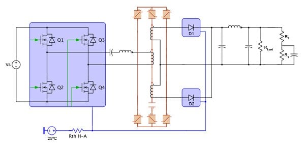
Figure 1: LLC resonant converter
Operation of LLC converter and estimating switching losses
The LLC converter is often operated under zero-voltage switching (ZVS) operation where the FETs (e.g., Q1) are turned on when the current is still flowing in its anti-parallel diode (e.g., D1). Therefore, only the forward voltage drop of the diode is applied to the FET, which is small compared to the DC input voltage. This results in negligible turn-on loss in the device and contributes to the reduction of overall losses. During ZVS operation, the FETs are turned off in a region where they conduct current. This results in hard-switching of the devices, generating turn-off switching losses, as shown in Fig. 2.

Figure 2: Zero-voltage switching scheme
PLECS uses ideal switches to model the power semiconductors, and switching losses are calculated using look-up tables. The data is input as energy loss as a function of blocking voltage, conducting current, and junction temperature. During the soft-switching turn-on event, zero switching losses are simulated, while the hard-switching turn-off switching losses are calculated from the circuit dynamics as a turn-off energy impulse. The look-up table approach for simulating switching losses was shown to have good correlation with hardware measurements in [2].
During turn-off and turn-on events, the body capacitor of each FET is charged and discharged, respectively. For circuits where the FETs (not the reverse diode) experience hard-switching during turn-on, the charge stored in the body capacitor is dissipated through the FET, adding to the switching losses. These losses can be captured in simulation (without adding a capacitor parallel to the FET) by simply including them in the look-up tables for the losses. When measuring the switching energy losses of FETs for certain operation points to generate the loss look-up table, it is important to include the charge stored in the FET body capacitor in the loss measurements. A major advantage of ZVS for FETs, in addition to eliminating turn-on losses, is that the energy stored in the body capacitance is recycled into the circuit [3], assuming there is enough blanking time between turn-off of Q1/Q4 and turn-on of Q2/Q3. Therefore, in soft-switching topologies operated with ZVS, turn-off losses can be overestimated by 10 to 20 % [4], if the effects of the capacitive elements are not reflected in the loss look-up tables.
Variable-frequency modulation
Frequently, to generate PWM signals in simulation, a duty cycle value is compared against a fixed-frequency triangular waveform. Such simplified models have inherent limitations in comparison to the functionality provided by real MCU peripheral modules. As a result, the system model fidelity is substantially reduced and effects critical to the power controls may be lost or inaccurately simulated. In [1] we discussed the efficient modeling of high-fidelity peripheral modules. A characteristic of these models is the ability to operate the high-fidelity PWM peripheral module with variable-frequency. The frequency and duty cycle are provided as inputs to this peripheral module. These inputs are sampled to update the PWM signal for the next switching period. The user can dynamically update the frequency and duty cycle in simulation, and therefore efficiently implement a variable-frequency modulator, as is needed for an LLC converter.
Modelling of magnetic device
Conventionally for dynamic circuit simulation, the magnetic devices are modeled directly in the electrical domain, in which magnetic coupling between windings are realized either with mutual inductances or ideal transformers and magnetizing inductances. However, the electrical equivalent circuit bears little resemblance to the physical structure of the magnetic component. For example, parallel flux paths in the magnetic structure are modeled with series inductances in the equivalent circuit. PLECS provides magnetic modeling capabilities based on the permeance-capacitance approach [5], allowing the user to build up a magnetic circuit to represent the iron core geometry and windings allocation intuitively, as well as include nonlinear effects such as saturation. In the LLC resonant converter presented here, the high-frequency transformer model is composed of two E-shape core components with an air-gap on the middle leg, and three windings, as shown in Figure 3. The geometric parameters of the iron core in this example are per the “E70/33/32” device specification from EPCOS, while material parameters regarding the saturation effect come from the B-H curve in the ferrite N87 datasheet. The winding turns values are chosen to achieve the expected magnetization inductance.

Figure 3: High-frequency transformer model using saturable magnetic elements in PLECS
Simulation results
A 200 VDC input is connected to the DC-side of the full-bridge. A slew rate is applied to the converter to limit the rate of change in output voltage during a change in the reference voltage. Additionally, a soft start algorithm is employed to limit the rate of change in commanded voltage during startup. This is reflected on the startup transient as the output voltage incrementally ramps up. After the soft-start, a voltage controller is used to control the switching frequency of the full-bridge. The system reaches the desired 300 VDC output after 20 ms. The thermal system has a smaller time constant, reaching steady-state after 40 ms. Figure 4 shows the transient simulation of the LLC converter from startup.
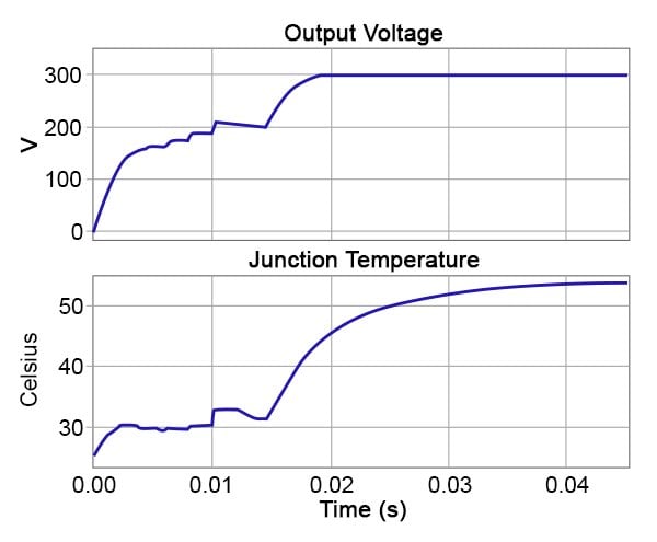
Figure 4: Startup transient simulation result for LLC converter
Figure 5 shows the operating points of the core on the B-H curve during a transient simulation to steady state. Engineers can size their magnetic component using the saturable core component to operate the system at the desired point of the B-H curve.

Figure 5: Operating region of the saturable core
ZVS of the FETs allows the converter to be operated with reduced switching losses, as the anti-parallel diode conducts the current when the turn-on gating signal is applied. The FET starts to conduct as the current direction becomes positive through the device. This results in zero turn-on switching losses. The FET is turned off at an instant when current is flowing through the device, resulting in hard-switching and turn-off switching losses. Figure 6 shows the gating signal and current of Q1. When the current is less than zero the anti-parallel diode is conducting. Figure 6 also shows the switching energy losses. There are no switching losses due to the soft-switching during turn-on of Q1 but the 0.3 mJ energy impulses reflect the turn-off losses due to hard-switching. The body capacitor’s energy storage is not included in the look-up table for this model; therefore the turn-off loss yields a maximum 20 % overestimate, as previously discussed.
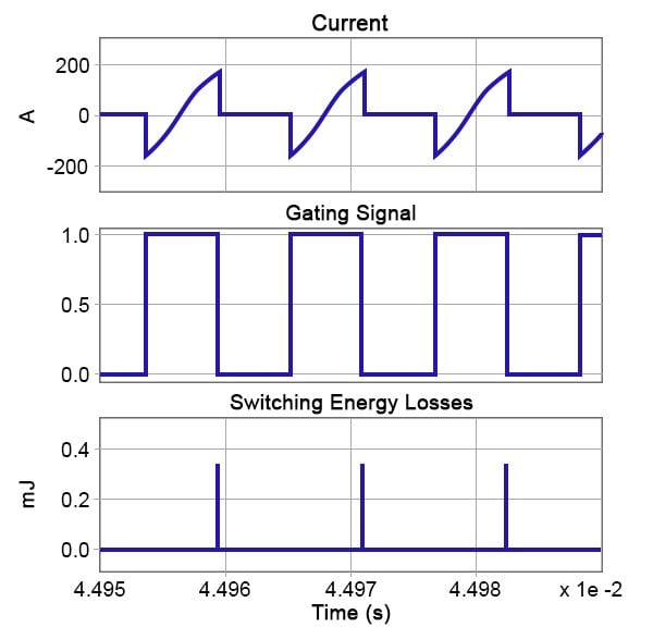
Figure 6: Steady-state waveforms showing current through Q1 and D1, FET gating signal and switching losses
Conclusion
The modelling and simulation of a resonant LLC converter has been presented in this article. PLECS permits analysis of transient effects from multiple physical domains in a single system model without excessive simulation times. This provides an effective and accurate means to investigate and address issues related to compact power supply design. Further, high-fidelity peripheral models allow designers to simulate the LLC under variable-frequency operation. Such comprehensive models provide power electronic designers with more insight into the system before hardware is built, leading to time and cost savings. www.plexim.com
About the Authors
Munadir Ahmed works as the Applications Engineer at Plexim Inc. since August of 2013 where he is responsible for the development of advanced simulation models for power electronic demo models, application notes and training modules; deliver technical workshops, seminars and video tutorials to educate participants in modelling PLECS and represent Plexim at customer visits, trade shows and conferences as well as report customer feedback to the developers. He earned his Bachelor of Arts in Mathematics, Physics and Statistics at Macalester College. He also holds a Master's Degree in Electrical Engineering at Purdue University.
Min Luo works as the Applications Engineer at Plexim since December 2012 where he is particularly skilled in C programming and power electronics. He holds both a Bachelor's Degree and a Master's Degree in Electrical and Electronics Engineering earned at Tsinghua University and RWTH Aachen University respectively.
Reference
- Prausse, F.; Ahmed, M., “Efficient Microcontroller Peripheral Modeling with PLECS”, Bodo’s Power Systems, July 2014 Issue, pp. 34-37
- Munk-Nielsen, S.; Tutelea, L.N.; Jaeger, U., “Simulation with Ideal Switch Models Combined with Measured Loss Data Provides a Good Estimate of Power Loss”, IEEE Industrial Application Conference, vol. 5, 2000, pp. 2915-2922
- Erickson, R.; Maksimovic, D., “Fundamentals of Power Electronics”, 2nd Edition, Springer, 2001, Chapter 19
- “A More Realistic Characterization of Power MOSFET Output Capacitance Coss”, International Rectifier Application Note, AN-1001 [5] Allmeling, J.; Hammer, W.; Schönberger, J., “Transient simulation of magnetic circuits using the permeance-capacitance analogy”, IEEE 13th Workshop on Control and Modeling for Power Electronics (COMPEL), 2012, pp.1-6
This article originally appeared in the Bodo’s Power Systems magazine.
Related Content