Facebook
 Google
 GitHub
 Linkedin
PLECS Goes Real-Time: A New HILSystem for Power Electronics
This article introduces Plexim's PLECS RT Box and its benefits for system modelling, design, simulation and testing of power electronics systems.
Introduction
Designing power converters is a complex task requiring advanced tools and processes. Power converters are sophisticated systems composed of multiple subsystems, including hardware and software components. Consequently, development and testing of power converters means optimizing multiple aspects that need to be explored, developed and tested in parallel, until the complete system is available for final validation.

Figure 1: Conventional design flow
The conventional “waterfall” or “V” development process heavily emphasizes the solid upfront definition of system requirements, cascading into definition of a set of subsystem requirements. Subsystems can then be developed concurrently and independently according to well-defined specifications, until they are ready for integration and validation. The challenge with this approach is its strong dependence on the relevance and accuracy of initial requirements driving the entire development process. If requirements are improperly defined, subsystems may be incompatible. Furthermore, the waterfall method cannot account for shifting market conditions or changing customer requirements. In the worst case, the outcome of a long development process could be a nonsaleable product.
Recognizing the drawbacks of the waterfall process, many industries have moved to more agile development [1], based on multiple short design iterations rather than one linear development period. This approach offers the advantage of multiple opportunities to learn lessons and adjust system and subsystem requirements. Contrary to the waterfall method, where value is only generated at the end of the development process, a more agile and incremental process may yield new results and knowledge with each design iteration.

Figure 2: Agile design flow
Independent of the methodology used, a modeling and simulation tool such as PLECS can be tremendously beneficial to power electronics engineers. In a waterfall process, efficiently modeling the complete power converter system is particularly useful when deriving system and subsystem requirements.

Figure 3: Applicability of PLECS to agile design flow
However, a circuit simulator is even more valuable (and critical) to agile developers. Since individual subsystems evolve at different rates and after different iteration counts, it is more difficult to perform early system testing without a virtual environment such as a PLECS simulation model. In other words, a circuit simulator can be a critical tool to keep the different subsystems in sync during their respective design iterations.
Plexim is continuously adding new functionalities to its PLECS product line to better assist modern power electronics development teams. “In-the-Loop” methodologies are extremely valuable for parallel and iterative development projects. Starting with the introduction of PLECS' control domain and C-Script block in 2009, followed by the Processor-in-the-Loop (PIL) tool in 2014, Plexim now provides solutions for real-time Hardware-in-the-Loop (HIL) testing.
This article introduces Plexim's new real-time platform and illustrates the applicability of real-time simulations in the general context of modern product development.
PLECS Tools
At the core of PLECS is the PLECS circuit simulator. It was specifically designed to model power converters, including the system in which they operate. Features of PLECS include:
- Ease of use
- Ultrafast simulation speed
- Numerical robustness
- Extensive and open component library
- Support for multiple physical domains
With PLECS, the engineer can quickly sketch out the complete power conversion system at the beginning of the development process, and improve the model in a top-down fashion as the design evolves. Initially, the model is of relatively low fidelity, but useful to derive system and subsystem requirements and make early top-level design decisions. Over time, the model's fidelity and quality increases as specific components are selected and measurements are available to fine-tune the models.

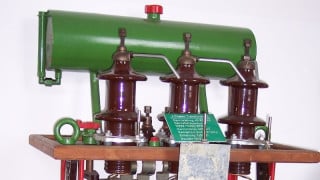
Figure 4: PLECS system model
Once a PLECS system model is created, it can be used as a virtual system test bed. For example, the model can be utilized to test and develop the “control software” subsystem if it adequately represents the most recent “control hardware” and “power hardware” subsystem iterations. Therefore, as long as a PLECS system model is maintained during an agile development process, it can serve as the virtual environment for system testing, long before actual system integration takes place.
As subsystem development becomes more mature, prototype software is written, and prototype hardware built, the engineer can tie such prototypes “into the loop”. For example, with the software-in-the-loop (SIL) approach, embedded code can be executed within the PLECS system model (using PLECS C-Script or DLL blocks).
For higher fidelity system testing, embedded code can be executed on the actual embedded processor and co-simulated with a PLECS model. This method is referred to as PIL and is discussed in detail in [2]. With PIL, platform-specific software defects, such as overflow conditions and casting errors, can be detected. A PIL co-simulation can also expose and analyze potential problems related to the multi-threaded execution of control algorithms, including jitter and resource corruption. The PLECS PIL package includes a PIL Framework library with support for the most relevant processor families used in power conversion and motor drive applications today. A set of high-fidelity peripheral models is also included. These accurately model the behavior of target-specific MCU peripherals such as ADC, PWM, and Capture modules. See [3] for more detailed information on MCU peripheral modeling with PLECS.
Once the control hardware has sufficiently evolved, developers can proceed to HIL testing, where the entire control hardware is tested in conjunction with a PLECS system model. This approach is fundamentally different from the system testing mentioned so far, because the PLECS model now must execute in real-time. Contrary to SIL and PIL, where control code execution is synchronized with an offline simulation, interfacing with physical control hardware requires generation and measurement of real-time analog and digital signals. Consequently, the PLECS model can no longer be executed on a conventional desktop PC, but must run on specialized real-time hardware, such as the new PLECS "RT Box".
Plexim also offers the PLECS Coder. It is capable of generating C code from a PLECS model for execution on real-time hardware. This requires the simulation model to be discretized to run at a fixed sampling frequency. Due to the fast time constants inherent in power conversion systems, the step size typically is on the order of microseconds. The ideal step size is a compromise between system model fidelity and the accuracy of the simulation results. If the step size is too small, the real-time hardware may not be able to execute the system model fast enough. If the step size is too large, unacceptable fidelity of the digital and analog signals generated by the real-time hardware may occur.
To assist the developer with this tradeoff, the PLECS Coder supports simulating generated discretized code within PLECS before it is deployed onto the real-time hardware. This permits inspecting the signal waveforms for different use cases and ensuring they are accurate enough for system testing purposes.
Specifically for real-time code generation, the PLECS library now includes a new component category called “Power Modules”. Power Modules implement the most frequently used powerstage topologies, such as choppers, half-bridges, 3-level half-bridges and cascaded topologies, in a fashion ideal for real-time simulation. With these specialized components, it is possible to run real-time models containing a large number of switches.
The real-time code generated by PLECS is suitable for execution on many real-time platforms such as Opal-RT and dSpace systems. Additionally, to provide a completely optimized solution with a unified user experience, Plexim is now offering its own real-time platform, "RT Box".
PLECS RT Box
The PLECS RT Box is a state of the art real-time simulator based on a 1 GHz Xilinx Zynq SOC. With its 64 digital and 32 analog I/O signals, the RT Box is well equipped for the HIL testing of complex power converter systems.

Figure 5: RT Box front

Figure 6: RT Box back
The PLECS RT Box is designed as a compact desktop unit (24 x 10 x 30 cm) and is competitively priced. For more details on pricing please contact: [email protected]
The unit also provides access to a 4-lane high-speed serial interface so it may be scaled up for more demanding HIL applications, such as modular multi-level HVDC converters.

Table 1: RT Box specifications
When evaluating real-time simulators, it is useful to consider the following key characteristics:
- Calculation speed
- Sample rate and I/O latency
- Signal resolution
- Model implementation flexibility
As mentioned earlier, power electronic systems contain small time constants due to their inherently switched nature. Though it is not necessary to simulate the transient turn-on and turn-off waveforms of each switching event, the switching frequency harmonics and PWM resolution result in high-frequency components. These must be accurately measured and reproduced. Consequently, real-time simulators for power conversion systems execute models at a much higher rate than typically encountered in other HIL applications. With fast-switching wide-bandgap semiconductor devices pushing practical switching frequencies to ever higher levels, speed requirements for real-time simulation will increase even further.

Figure 7: Roundtrip latency
The most meaningful metric when comparing the "speed" of real-time simulators is overall roundtrip latency, i.e. total time elapsed from measuring inputs to updating outputs. This is the sum of delays associated with the ADC, model update (calculation), DAC, plus the latencies associated with transferring data.
Individual delays depend on the underlying hardware topology. Several approaches exist, each with advantages and disadvantages.
The first approach uses, at its core, a digital signal processor (DSP). DSPs are very effective number crunchers with complex instruction sets, resulting in short model update times. Unfortunately, the advantage of calculation speed is normally offset by poor I/O latency, caused by the commonly used PCIe bus protocol.
The second type of HIL system is FPGA-based. In this case, the model is fully calculated by the programmable logic cells. Direct access to I/O components is possible with minimal latency. Using an FPGA permits parallelization of certain calculation tasks, further improving speed. However, the challenge with FPGAs is limited numerical accuracy and reduced flexibility. Consequently, real-time models must be custom-designed and highly optimized by FPGA experts. FPGA-based HIL systems commonly come with a set of predefined topologies for the user to select. This is especially problematic if a HIL system is being used to develop and analyze new converter topologies. Such solutions are substantially less transparent and make it difficult for users to assess if the real-time model truly reflects the simulated system as intended.
With the goal of combining the advantages of both approaches described so far, the third solution uses a system-on-a-chip (SOC) device, comprising both processor cores and FPGA fabric. Though the I/O latency is slightly larger than with a pure FPGA solution, the calculation power of the associated processor cores offsets the difference and permits comparable roundtrip latencies, with the advantage of increased flexibility. The SOC approach therefore allows a more accurate real-time representation of the original offline system model and does not limit converter topology.
Table 2 summarizes the comparison:

Table 2: Comparison of approaches
The PLECS RT Box is based on a SOC, optimizing the tradeoff of I/O latency, numerical performance and modeling flexibility. Excellent signal resolution is achieved by using the latest generation of 16-bit ADC and DAC chips with sample rates of 2 MSPS. The digital capture module can resolve PWM signals at 7 ns.
When used with the PLECS circuit simulator and PLECS Coder, the PLECS RT Box provides a complete and consistent solution for system-level verification and validation of control software and hardware subsystems.
Outlook
The PLECS RT Box is designed with the future in mind. With its high-speed communication interface, the RT Box is prepared for operating multiple units in parallel or in a master/slave arrangement. Such configurations can leverage new PLECS solver and coder technologies currently under development, making the platform even more powerful and suitable for large scale and complex real-time simulations.
Summary
System modeling is an indispensable part of agile power electronics product development. It facilitates early design decisions and formulation of system and subsystem requirements. A system model maintained throughout the product development also serves as a virtual system test bed for subsystem iterations. “In-the Loop” testing (SIL and PIL) can be applied very early in development, minimizing risk of subsystem incompatibility. As control hardware becomes available, HIL testing can be used to increase test coverage.
With the introduction of the PLECS RT Box real-time platform, Plexim's product portfolio now covers all aspects of virtual system testing, offering a one-stop solution with a unified user experience and the trusted power of PLECS “under the hood".
About the Author
Beat Arnet works as the General Manager North America at Plexim since June of 2012. He is highly skilled in the field of power electronics, electric vehicles and engineering management as well. Throughout his career, he already accomplished 5 patents. He earned his Ph.D. in Electrical Engineering at the Swiss Federal Institute of Technology Lausanne (EPFL).
Felix Prausse works as an Application Engineer at Plexim GmBH since August of 2012 where he is responsible for development, support and training in the field of simulation of power electronic circuits. He has significant experience in research in the field of control and simulation technology and in building automation and process automation.
References
- “Being Agile” Apress, October 2013, Mario E. Moreira
- “Developing Embedded Controls using PLECS/PIL”, Bodo’s Power Systems, May 2015 Issue, pp. 44-46, Beat Arnet
- “Efficient Microcontroller Peripheral Modeling with PLECS”, Bodo’s Power Systems, July 2014 Issue, pp. 34-37, Felix Prausse, Munadir Ahmed
This article originally appeared in the Bodo’s Power Systems magazine.