Facebook
 Google
 GitHub
 Linkedin
Lighting up the Theatre Safely
This article gives an overview of DMX512A, showing and explaining recommended electrical and electronic requirements, and how the protocol was implemented.
The recommended electrical and electronic requirements for the DMX512A lighting communications protocol
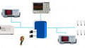
The most common lighting communications protocol used in theatrical lighting is DMX512, and it is also often found in architectural and other lighting systems. Uses of the standard include dimming theatrical lights, running colour mixing lighting fixtures, robot scanner lighting fixtures, strobe lights and fog machines. Some vendors use it to control commercial or domestic lighting fixtures and even giant high definition television displays have been built using multiple DMX512 universes.
The standard was created in 1986 by the United States Institute for Theatrical Technology (USITT) to be a more reliable replacement for the 0 to 10V standard commonly used at the time. In 1998, it was taken over by the Entertainment Services & Technology Association (ESTA). It became DMX512A in 1998, and was revised in 2008. It has been an Ansi standard since 2004 (Ansi E1.11- 2008). Since 2011, the standard has also been maintained by PLASA in Europe.
Due to there being no error checking, there are some restrictions of use. Basically, any use that could potentially harm or kill a human or animal is not allowed. This includes, but is not limited to, moving stages, moving trusses and pyrotechnic control.
This simple, single master serial protocol uses the RS485 electrical layer at a data rate of 250kbaud, no error checking and up to 512byte of data. A DMX512 universe is made up of 512 channels of information sent from a single controller. Multiple universes can be created by using additional controllers. The electrical requirements are very well defined in the specification, including what circuit designs to use and the exact type of cable and connectors that are allowed. Despite this, there are many manufacturers that do not follow the specification and use invalid circuit layout and incorrect connectors, which can cause issues with compatibility and reliability.
The data packet is retransmitted continuously, which helps correct any data glitches. If no packet has been transmitted within one second, then most receivers will switch to a default setting or to an off mode. The maximum refresh rate for 512 channels is 44 updates per second, which allows for nice dimming with little or no visible flicker on incandescent bulbs. LEDs may require smart control to smooth out fading.
Electrical requirements
The electrical requirements are based on the RS485 standard, with slight variation. It uses RS485 differential transceivers, maximum transmission line length of 1200m, and up to 32 receivers per RS485 transmitter. The driver output range is ±1.5 to ±6V and receiver sensitivity is ±200mV.
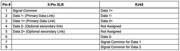
Figure 1: Connector pinouts
DMX512A requires the receivers to be isolated, which helps avoid earth loop and potentially lethal voltage differences. Many low-cost receivers, often used by DJs and for party lighting, are still non-isolated and can cause communications issues or be a safety hazard, especially if part of a larger network of lights.
Cable requirements are specified as a cable with a nominal characteristic impedance of 120 with a shield and two twisted pairs. Only one of the pairs is generally used, as the second pair is set aside for a secondary channel that is not commonly used. Because of this, many DMX512 cables use a single pair. Due to these requirements and the hard-wearing environment of stage lighting, there are some cable manufacturers that make DMX512 specific data cable that is flexible and very heavy duty with DMX, DMX512 or DMX512A printed on the cable itself.
The DMX512A specification introduced the use of Cat 5E cable and RJ45 connectors strictly for use in permanent installations, where the cable is not being moved, and the connectors are only used on occasion. This is more cost-effective, but would not last in a non-permanent setting.
The standard only specifies the use of five-pin XLR type connectors for DMX512 communications, and DMX512A added the use of RJ45 connectors for permanent installation. For the XLR connectors, the plug is used for the DMX in and the socket for DMX out. The pinouts for the five-pin XLR and RJ45 are shown in Figure 1.
Despite the standard specifying the connectors, many low-cost manufacturers use three-pin XLR connectors commonly found in professional microphones. This introduces a number of issues from different pinouts, and the common mistake of using microphone cable instead of DMX data cable, to plugging of DMX and audio equipment together accidentally. It is highly recommended that the user comply with the DMX512A specified cables and connectors to avoid these issues, and to ensure DMX512A compliance.
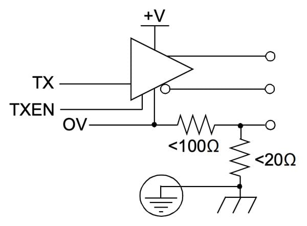
Figure 2: Controller transmitter circuit
Circuitry
For the controller, the transceiver is usually a ground-referenced transmitter, although it is possible to have it isolated. The recommended circuit from the DMX512A specification is in Figure 2 and shows how to connect the signal and chassis (earth) grounds using resistors. Even though the resistors are optional, they can possibly reduce earth loop issues if they are included in the design. More details are found in Ansi E1.11-2008.
The receiver is isolated, as shown in Figure 3. The resistance from any pin on the DMX connector to chassis ground must be greater than 22M at 42V. An optional capacitor may be fitted between the data link common and the chassis ground for radiofrequency bypass.
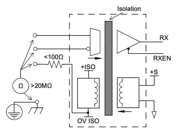
Figure 3: Receiver circuit
DMX512 uses a daisy chain connection topology, as shown in Figure 4. Up to 32 receivers can be daisy-chained from a single driver with a 120Ohm termination resistor at the far end of the chain. To achieve this, there are two connectors on each receiver, often labelled “DMX in” and “DMX out”.
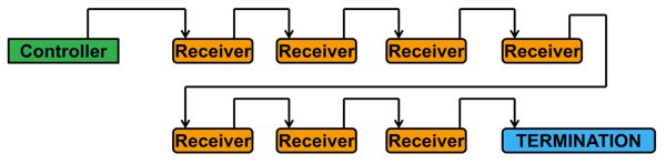
Figure 4: DMX512 daisy chain
These two connectors have the data and ground lines connected between them, so it electrically passes the data along the chain. To connect more than 32 receivers to a single controller, DMX splitters are required. These can be as simple as an isolated RS485 receiver that feeds to multiple RS485 transmitters or a more elaborate system that uses microcontrollers to capture and retransmit data with the possibility of limited back channel capability. Because of this, receivers with back channel capability should be connected directly to the controller’s bus to avoid potential problems.
The standard does allow for bidirectional communications, and these are covered in Ansi E1.11-2008 Annex B – Enhanced DMX512. Communications can operate in full or half-duplex modes using just the primary data link, or using both primary and secondary data links. The data protocols and any timing requirements are not specified in the standard. To achieve bidirectional communications, all the transceivers must be bidirectional and controlled using an additional IO pin. In normal operation, the controller should be configured for transmit mode and the receiver for receive mode.
DMX512 library
The DMX512 library is completely interrupt driven and requires the use of a EUSART and one timer. The timer generates the break and the MAB (mark after break) timing for the controller and the data time out for the receiver. The timer also generates millisecond, minute and hour ticks and counts that can be accessed for general use. Using the EUSART found on many Microchip PIC microcontrollers, the break can easily be detected using the framing error interrupt. The data rate of 250kbaud is a clean divide down from common oscillator frequencies, such as 4, 8 or 32MHz, which results in a theoretical 0% data rate error. These features make implementing DMX512 relatively simple.
The library currently implements a DMX controller, receiver or both, depending on how it is configured. A future version may add half-duplex communications capability and possibly a basic implementation of remote device management (RDM). Currently, the library is targeted at the Microchip Technology 8bit microcontroller family with a EUSART, but can be easily ported to the 16 and 32bit families and some non-EUSART parts.
Conclusion
This article gives an overview of DMX512A, showing and explaining recommended electrical and electronic requirements, and how the protocol was implemented in the Microchip Technology DMX512 library.
About the Author
Michael Pearce works as an Applications Manager at Microchip Technology since April 2015 where he is responsible for managing a team of engineers and technicians to design and develop hardware to support the Microchip Technology 8 bit application engineering teams. He is an experienced application manager with a demonstrated history of working in the semiconductors industry. Strong information technology professional skilled in Atmel AVR, Management, Electrical Engineering, Microchip PIC, and Electronics.