Facebook
 Google
 GitHub
 Linkedin
Over-Voltage Protection for RS485 Bus Nodes
This article focuses on RS-485 transceiver protection against large over-voltages (OVP) and the difference between over-voltage and transient protection.
Robustness and reliability have made RS-485 the industrial workhorse over the past 40 years. Its large differential signal swing of 1.5V minimum and reliable operation over a wide common-mode voltage range of -7V to +12V have catapulted the RS-485’s widespread deployment. Initially used as a communication network in laboratory instrumentation, RS-485 has spread to control networks in industrial and building automation, PLC networks on the factory floor, process control, commercial heating, ventilation and air-conditioning systems, seismic networks, traffic monitoring systems, and alarm indication systems in oil rigs, coal mines and the petrochemical industry.
Along with the growth and widespread use of RS-485 came an increasing demand for greater robustness such as:
- Higher output voltage swing to ensure higher noise margin
- Wider common-mode range to allow for larger ground potential differences between remote bus nodes
- Increased tolerance to electrostatic discharges caused by field personal
- Stand-off capability or protection against persistent over-voltages far beyond the maximum transceiver supply level specified in datasheets
It is the latter point this article focuses on: RS-485 transceiver protection against large over-voltages. First, we’ll discuss the difference between over-voltage and transient protection. Then, we’ll look at what it takes for an over-voltage protected (OVP) transceiver to be successful, and how meaningful an integrated transceiver is versus a discrete solution using a standard transceiver. Finally, we’ll compare some performance characteristics of a 20Mbps high-speed OVP transceiver to an inferior OVP version.
Over-Voltage Protection versus Transient Protection
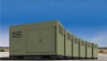
The 24V and 48V DC supplies in industrial and telecom systems are commonly distributed through the same conduits as the data lines of an RS-485 network. Figure 1 shows a number of causes for over-voltage occurrences.

Figure 1: Multiple causes for over-voltage faults when data lines share the same conduit as DC power lines
If a DC supply shares the same connector or screw terminal block with the data lines of an adjacent bus node circuit, miss-wiring faults can occur that connect one or more supply conductors with the transceiver bus terminals.
Another failure cause is the layout of the conduit. Sharp bends often violate the minimum cable radius specified for data and supply cables. Over time, the increased mechanical pressure on the cable will cause a break in the insulation, causing shorts between power and data lines. This can also happen when machinery or equipment is placed against a conduit, thus crunching the cable. The duration of over-voltage events can last for minutes and up to weeks until their causes are eliminated.
Much shorter over-voltage events, such as over-voltage transients, can occur due to load switching activity in the power distribution system and lightning strikes, which induce high surge currents and voltages into the data lines.
Engineers new to over-voltage protection often assume that adding external transient voltage suppressors (TVS) to a non-fault protected, standard transceiver ensures protection against short- and long-term over-voltages. This is not true because the maximum power the TVS can absorb decreases with increasing transient duration, which is shown in Figure 2.

Figure 2: Peak pulse power versus pulse duration characteristic for a 600W TVS
The diagram in Figure 2 shows a 600W TVS rated at 1ms pulse width. Note that the time axis ranges from 10μs to 10ms with power levels of 6000W and 200W respectively. From this characteristic, it should be clear that exposing a TVS to long-term over-voltages would fry the device.
Therefore, to protect your bus nodes against the wide range of over-voltages, you need fault-protected transceivers, such as Intersil’s ISL3245xE family. These transceivers provide protection against DC over-voltages of up to ±60V and transient over-voltages of up to ±80V.
Integrated versus Discrete Fault Protection
Occasionally the question arises: Why not use a non-fault protected, standard transceiver and a few discrete low-cost transistors with sufficient high voltage breakdown for over-voltage protection? The answer is simple: A discrete solution adds more cost and development time, and it consumes more space than a fault-protected transceiver.
Let’s assume the function of the fault-protected, half-duplex transceiver in Figure 3 is to be accomplished with a discrete design using a standard transceiver. First, the transmit path and the receive path must be separate to allow for the implementation of a boosted output stage with high standoff voltage. This requires the use of a full-duplex transceiver. The output stage could be realized with four discrete transistors or an integrated h-bridge whose control inputs require the conversion from RS-485 bus signals into TTL or CMOS logic levels. This would require a drive logic circuit between the transceiver and the discrete output stage.
In the receive path, a discrete voltage limiter, consisting of Zener diodes and series resistors, must be implemented to limit the bus voltage during an over-voltage event, otherwise it remains transparent.

Figure 3: Integrated versus discrete over-voltage protection designs
Figure 3 shows that the discrete solution already becomes cumbersome by merely providing the basic functions for over-voltage protection, while still lacking a current limiter, which is a vital component for over-voltage protection.
Current limiting is a critical function during over-voltage events when the driver is actively driving the bus. Because the enabled driver presents a low-impedance connection to ground, bus currents flowing through the driver become huge, damaging the device if they are not limited.
Current Limiting of Fault-Protected Transceivers
Fault-protected transceivers with common-mode ranges wider than specified in the RS-485 standard require double fold-back current limiting within the driver stage. Figure 4 shows the current limiting function of the ISL3245x family of fault-protected transceivers that operate over the wide common-mode range of ±20V.
Here, the first fold-back current level of 63mA ensures that the driver never folds back when driving loads within the entire 40V common-mode voltages. The very low second fold-back current setting of 13mA minimizes power dissipation if the driver is enabled when a fault occurs. This current limiting scheme ensures that the output current never exceeds the RS-485 specification, even at the common mode and fault condition voltage range extremes.
In the event of a major short-circuit condition, the transceivers also provide a thermal shutdown function that disables the drivers whenever the die temperature becomes excessive. This eliminates any power dissipation and allows the die to cool. The drivers automatically re-enable after the die temperature drops by 15°C. If the fault condition persists, the thermal shutdown/re-enable cycle repeats until the fault is cleared. Receivers stay operational during thermal shutdown, and fault-protection is active regardless of whether the driver is enabled, disabled, or the IC is powered down.

Figure 4: Driver output current limiting versus over-voltage
Adding Lightning Protection to Fault-Protection
The energy of over-voltage transients caused by lightning can easily exceed the transceiver’s fault protection and must be absorbed by external TVS diodes. Two conditions need to be satisfied when adding external TVS devices to a fault-protected transceiver:
- The TVS breakdown voltage must be 1V higher than the highest common-mode voltage of the application or the maximum DC-supply, whichever is higher. For applications only exposed to the standard common-mode range of -7V to +12V, VBR-min ≥ 13V, for bus lines running adjacent to DC-power lines with 24V nominal supply, VBR-min should be ≥ 31V, as 24V systems are known for excursions of up to 30V.
- The peak clamping voltage of the TVS must be below the transceiver’s maximum fault-protection levels.
Figure 5 shows the respective circuit as well as the TVS switching characteristics with breakdown and clamping voltages, VBR and VCL, and compares them to the maximum common-mode, DC-voltage, and fault-protection levels.

Figure 5: TVS V-I characteristic in comparison to VCM-max and VDC-max
Performance Comparison
Fault-protected transceivers with a wide supply voltage range enables designers to use the same device in 5V and in 3.3V low-voltage systems, which reduces logistics and can lead to an attractive price break for higher volumes.
Not all 3V-to-5V transceivers, however, provide sufficient drive capability at low supply. Figure 6 and Figure 7, for example, compare the output drive capability of the ISL32458E 20Mbps high-speed transceiver with a competing 10Mbps device, denoted as Competitor T, which also claims operation down to 3V.

Figure 6: At 3.3V supply, the ISL32458E provides a 1.5V output compared to the 0.9V of Competitor T

Figure 7: Competitor T’s output drops further when measured across its specified common-mode range
The typical characteristic of driving a purely differential load (Figure 6) already discloses the inferior output drive capability of Competitor T. At VCC = 3.3V Competitor T struggles to provide 50% of the 1.5V minimum VOD specified in RS-485, even without the burden of common-mode loading. In strong contrast, ISL32458E delivers a solid 1.5V across the 54Ω differential load.
When measured across the much narrower common-mode range (Figure 7), Competitor T’s VOD comes nowhere near the 1.5V minimum (dotted line) for the entire range. ISL32458E deviates only slightly down to 1.3V at the extremes of the standard common-mode range and quickly regains drive strength towards the outer limits of ±20V.
Another shortcoming of so-called 3V-to-5V transceivers is that they do not necessarily operate down to 3V. Figure 8, for example, shows that the Competitor T device stops operating at 3.15V, which is only 5% below the nominal 3.3V level. This, of course, requires a tighter tolerance of the linear regulator providing the transceiver supply voltage.
In comparison, the entire ISL3245xE family starts operating at a minimum supply of around 2V, thus not only ensuring true 3V operation, but also allowing for a relaxed tolerance specification of the voltage regulator.

Figure 8: ISL32458E stops operating below 2V, which is 1V less supply than Competitor T’s 3.15V
Conclusion
System designers are no longer required to choose between robust fault tolerance and high performance in RS-485 and RS-422 transceivers, as the ISL32458E and ISL32459E offer both. These transceivers feature ±60V over-voltage and ±15kV ESD tolerance, while including operation over 3V to 5.5V supply voltages. They also operate up to a 20Mbps data rate, and provide a ±20V common-mode voltage range. In addition, the ISL32459E provides a cable-invert function.

Table 1: OVP-Transceivers with 3V to 5V Supply and High ESD
This article originally appeared in the Bodo’s Power Systems magazine.
About the Author
Thomas Kugelstadt works as a Principal Applications Engineer at Intersil Corporation, now a wholly-owned subsidiary of Renesas Electronics Corporation. He is particularly skilled and has deep experience in analog circuit design, integrated circuit development and technical writing for contributed magazine articles. He earned his Master's Degree in Telecommunications and Control Engineering at Frankfurt University of Applied Sciences located in Germany.