 Facebook
 Google
 GitHub
 Linkedin
Lead-Acid Battery Basics
This article examines lead-acid battery basics, including equivalent circuits, storage capacity and efficiency, and system sizing.
Stand-alone systems that utilize intermittent resources such as wind and solar require a means to store the energy produced so the stored energy can then be delivered when needed and the resources are unavailable.
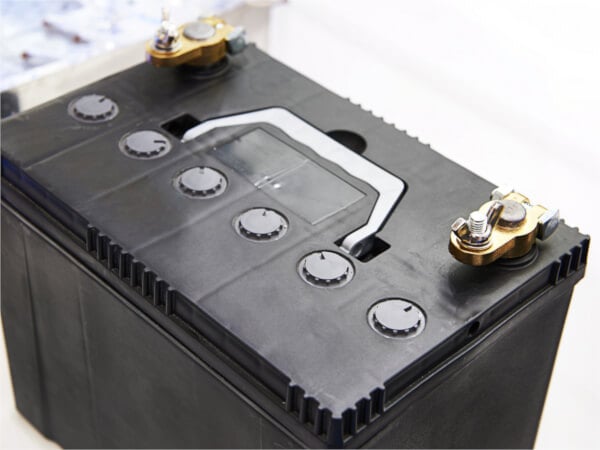
Image used courtesy of Adobe Stock
Advanced storage technologies and smart grid are still areas of research. For most small-scale, stand-alone systems, batteries are still the most economically sensible method of energy storage.
An ideal battery (without internal resistance) is one in which the voltage is a constant independent of the current provided. A real battery has some internal resistance. The equivalent circuit model for a real battery is an ideal battery in series with internal resistance.
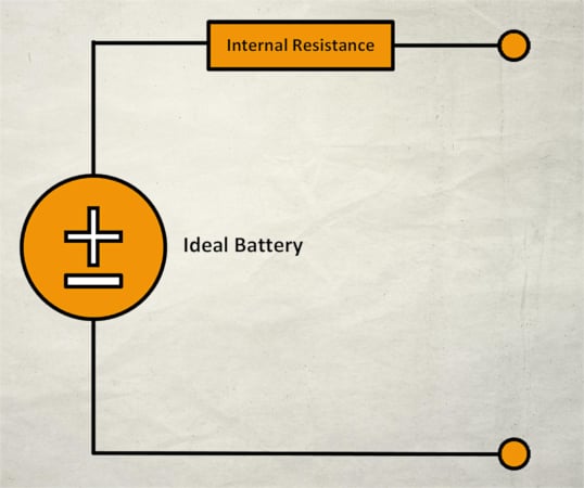
Figure 1. Equivalent circuit of a real battery. Image used courtesy of Ahmed Sheikh
The open-circuit voltage vs depends on the state of charge (SOC) and battery temperature. For a typical 12 V battery vs varies from 12.7 V fully charged to 11.7 V when the battery is almost fully discharged. Internal resistance RS is also a function of the state of charge and temperature. When the battery provides current, there is a voltage drop across RS, and the terminal voltage v < vs. To charge the battery, a voltage v > vs. must be applied to the battery terminals.
Example 1
A real battery consists of a constant voltage source with voltage vs = 12.7 V and an internal resistance Rs = 0.1 Ω. When connected to an external load, the current is 1.0 A.
The voltage drop across the internal resistance
\[\Delta v=IR_{s}=(1.0A)\times(0.1\Omega)=0.1V\]
Thus, the terminal voltage
\[v=v_{s}-\Delta v=12.7V-0.1V=12.6V\]
Lead-Acid Battery Cells and Discharging
A lead-acid battery cell consists of a positive electrode made of lead dioxide (PbO2) and a negative electrode made of porous metallic lead (Pb), both of which are immersed in a sulfuric acid (H2SO4) water solution. This solution forms an electrolyte with free (H+ and SO42-) ions. Chemical reactions take place at the electrodes:
\[+:PbO_{2}+4H^{+}+SO^{2-}_{4}+2e^{-}\rightarrow pbSO_{4}+2H_{2}O\]
\[-:Pb+SO^{2-}_{4}\rightarrow pbSO_{4}+e^{-}\]
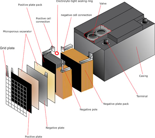
Figure 2. Lead-acid battery diagram. Image used courtesy of the University of Cambridge
When the battery discharges, electrons released at the negative electrode flow through the external load to the positive electrode (recall conventional current flows in the opposite direction of electron flow). The voltage of a typical single lead-acid cell is ∼ 2 V. As the battery discharges, lead sulfate (PbSO4) is deposited on each electrode, reducing the area available for the reactions. Near the fully discharged state (see Figure 3), cell voltage drops, and internal resistance increases. During charging, the applied voltage drives the reactions in the opposite direction. Cell voltage increases, internal resistance drops, and sulfate is removed from the electrodes.
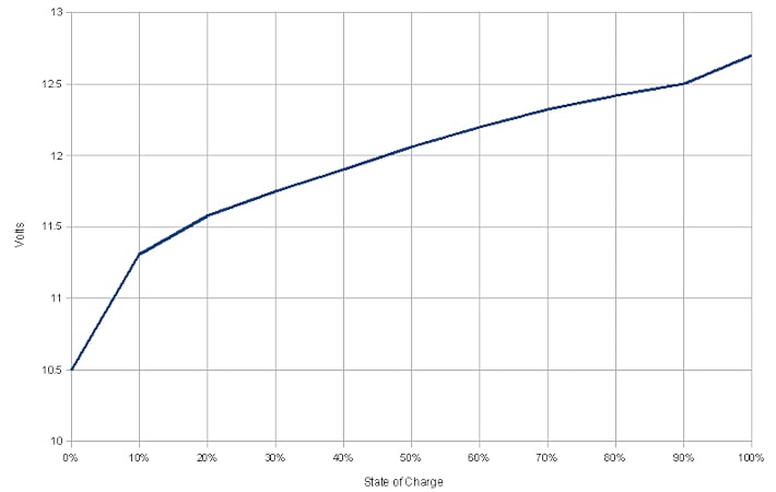
Figure 3. Lead-acid battery State of Charge (SoC) Vs. Voltage (V). Image used courtesy of Wikimedia Commons
For each discharge/charge cycle, some sulfate remains on the electrodes. This is the primary factor that limits battery lifetime. Deep-cycle lead-acid batteries appropriate for energy storage applications are designed to withstand repeated discharges to 20 % and have cycle lifetimes of ∼2000, which corresponds to about five years.
Storage Capacity
Battery capacity is reported in amp-hours (Ah) at a given discharge rate. For example, a 100 Ah, 20 h battery could deliver 5 A for 20 hours, at which point the battery would be fully discharged. The reported Ah capacity depends on the discharge rate. A 100 Ah battery delivering 5 A is said to be discharging at a C/20 rate where C is the Ah capacity, and 20 is the depletion time in hours. However, the same battery may not be capable of delivering 100 Ah at C/5 (20 A for 5 hours). In fact, rapid discharge results in a lower Ah capacity. Deep cycle batteries are typically specified in terms of C/20 and C/100 discharge rates.
Battery Efficiency
The energy supplied to a battery when charging at voltage vs, current IC, and time ∆tic is
\[E_{C}=v_{C}I_{C}\Delta t_{C}\]
If the battery is discharged at voltage v and current I for time ∆t, the energy delivered is
\[E=v I\Delta t\]
Energy efficiency is the ratio of the energy returned to the charging energy supplied.
\[\varepsilon=\frac{E}{E_{C}}= \Bigg(\frac{v}{v_{C}}\Bigg)\Bigg(\frac{I\Delta t}{I_{C}\Delta_{C}t_{C}}\Bigg)\]
The second term on the right-hand side \(\Bigg(\frac{I\Delta t}{I_{C}\Delta_{C}t_{C}}\Bigg)\) is the ratio of Ah delivered by the battery to the Ah provided to the battery during charging. This ratio is the Coulomb efficiency.
\[\varepsilon_{C}=\frac{I\Delta t}{I_{C}\Delta_{C}t_{C}})\]
The voltage efficiency is
\[\varepsilon_{v}=\frac{v}{v_{C}}\]
Thus, the energy efficiency is
\[\varepsilon=\varepsilon_{v}\times \varepsilon_{C}\]
A typical 12 V battery may be charged at a voltage of 14 V, in which case eve ≈ 0.8. The Coulomb efficiency is limited by water electrolysis and the release of hydrogen and oxygen gas (gassing) as the state of charge approaches 100 %. Over a charge/discharge cycle, act > 0.9. For these values, the energy efficiency ε ∼ 0.77. Regarding the equivalent circuit model of a real battery, this energy loss can be understood in terms of I2R losses in the internal resistor. More rapid charge or discharge rates (larger I) result in higher energy losses.
Battery Storage System Sizing
Most battery energy storage systems consist of a series-parallel combination of batteries to provide the required voltage and Ah capacity. The voltage is added for series batteries, but the current (and thus the Ah capacity) is the same for the combination as for a single battery. For batteries in parallel, the voltage across each battery is the same, and the current (and thus the Ah capacities) is added. Another consideration when designing a battery storage system is wire sizing. For the same amount of energy, batteries in series provide power at higher voltage and lower current than parallel batteries. This means that wire sizes can be smaller.
Example 2
System sizing. A storage system is required for an AC load of 10 kWh per day. The system voltage will be 24 V with an overall inverter efficiency of 80%. The storage system will utilize Trojan T-145 6 V batteries, which provide 260 Ah at a C/20 discharge rate and 287 Ah at a C/100 discharge rate. The system should be designed to provide five days of energy storage.
Because of losses due to DC to AC inversion, the DC load is
\[\frac{10kWh}{0.80}=12.5kWh\]
At a system voltage of 24 V, the daily capacity required is
\[\frac{12.5kWh}{24V}=520\frac{Ah}{day}\]
For five days, the total capacity is
\[520\frac{Ah}{day}\times5days=2600Ah\]
With 6 V per battery, a string of 4 batteries in series will provide the required 24 V system voltage. Each string, however, will only supply a fraction of the total required capacity. If each string is discharged to a 20 % state of charge, the capacity per series string is 80 % of the total capacity of an individual battery. Using the C/100 rate capacity
\[287Ah\times0.80=230Ah\]
To supply the full capacity will require connecting some strings in parallel. The number of parallel strings will be
\[\#=\frac{2600\,Ah}{230\frac{Ah}{string}}=11.3\]
If a slightly undersized system is sufficient, it will require a total of 44 batteries with 11 strings of 4 batteries in series.
Lead-Acid Battery Takeaways
Understanding the basics of lead-acid batteries is important in sizing electrical systems. The equivalent circuit model helps to understand the behavior of the battery under different conditions while calculating parameters, such as storage capacity and efficiency, which are crucial for accurately estimating the battery's performance. Proper system sizing is also critical in ensuring the longevity and reliability of the battery, and the detailed sizing example provides a practical guide for implementing these principles.


A Depth of Discharge of 50% is typically for lead acid batteries while 90% is typical for Li-ion batteries.
Any reason for considering 80% for lead acid batteries?