Facebook
 Google
 GitHub
 Linkedin
NEC Basics: Grounding and Bonding DC Systems Supplying Premises
Learn whether or not you should connect a direct current power supply to the ground.
Part VIII of Article 250 deals with grounding and bonding direct-current (DC) systems supplying power to premises. Some of these rules differ from those intended explicitly for alternating-current (AC) systems.

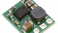
Image used courtesy of Pixabay
Although most electrical energy produced commercially is generated, transmitted, and distributed as alternating current (AC), a large percentage is utilized as direct current (DC). Examples are variable speed machinery with DC motors, electrochemical works, and critical areas with battery backup.

Image used courtesy of Freepik
DC motors are better suited for many industrial processes demanding high flexibility in speed and torque control.
The classification of AC power systems relies on the number of phases. DC power systems do not have phases but polarities, and the number of wires typically categorizes the arrangements. The two standard low-voltage DC distribution systems are two-wire and three-wire.
National Electrical Code Section 250.160 General Requirements for Direct-Current Systems
Direct-current systems must follow the rules in Part VIII of Article 250, and those sections not exclusive of alternating-current arrangements.
National Electrical Code Section 250.162 Circuits and Systems to be Grounded
Follow the grounding rules in sections 250.162(A) and (B).
Section 250.162(A) Two-Wire Systems
Ground two-wire systems supplying premises wiring at a voltage larger than 60 V but not higher than 300 V.
Figure 1 shows a grounded two-wire direct-current distribution system. The system employs a DC source and two wires to power the electrical loads. Like in batteries, the wire polarities are positive (+) and negative (-).
This rule does not specify which wire (polarity) must be grounded.

Figure 1. Two-wire direct current system. Image used courtesy of Lorenzo Mari
Exception N° 1. Systems supplying industrial equipment in limited areas equipped with ground detectors fitted next to, or integral to, the supply source.
Figure 2 shows a PDC ground-fault detector to monitor ground faults in a floating battery system.

Figure 2. DC ground-fault detector. Image used courtesy of Moore Industries
Exception N° 2. A system derived from a rectifier supplied by an AC system complying with Section 250.20, “Alternating-current systems to be grounded.”
Figure 3 shows a rectifier working with SCRs (silicon-controlled rectifiers).

Figure 3. SCR rectifier. Image used courtesy of Dynapower
Exception N° 3. DC-powered fire alarm circuits with a maximum current of 0.030 A, consistent with Part III of Article 760, “Power-limited fire alarm circuits (PLFA).”
Section 250.162(B) Three-Wire Systems
Ground the neutrals of three-wire systems supplying premises wiring.
Figure 4 shows a grounded neutral in a three-wire direct-current distribution system.

Figure 4. Three-wire direct current system. Image used courtesy of Lorenzo Mari
National Electrical Code Section 250.164 Point of the Grounding Connection
Section 250.164(A) Source Located Off-Premises
Make the grounding connection at one or more source stations. Do not connect at individual services or on the premises wiring. See Figure 5.

Figure 5. Grounding connection on an off-premises source. Image used courtesy of Lorenzo Mari
Section 250.164(B) Source Located On-Premises
There are three options for the grounding connection at on-premises sources:
- At the source–same point of connection as off-premises sources
- At the first disconnecting means or overcurrent protective device
- Employing other means with listed equipment identified for the use
National Electrical Code Section 250.166 Size of the Grounding Electrode Conductor
The size must be as specified in sections 250.166(A) and (B), except as permitted in sections 250.166(C) through (E).
Using a conductor larger than size N° 3/0 AWG copper or N° 250 kcmil aluminum or copper-clad aluminum is not required.
Section 250.166(A) Not Smaller Than the Neutral Conductor
Suppose the DC system consists of a three-wire balancer set or a balancer winding with the overcurrent protection required in Section 445.12(D). In that case, the minimum grounding electrode conductor size must be N° 8 AWG copper or N° 6 AWG aluminum or copper-clad aluminum, not smaller than the neutral conductor.
One way of obtaining a three-wire system from a two-wire system is by using a balancer set.
Figure 6 shows a balancer set consisting of two identical small shunt-wound DC machines, 1 and 2, mechanically coupled to a shared shaft, with each set of armatures and shunt field windings connected in series. The neutral wire and the connection to the ground begin at the common point of the armatures.
The main two-wire generator, G, supplies power to the system, and the balancer set keeps the same potential difference (V) on both wires.
Under balanced conditions, both balancers work as DC motors. Under unbalanced conditions, the machine on the light load side works as a DC motor. In contrast, the device on the heavily loaded side acts as a DC generator, compensating for the voltage imbalance. The balancing effect is limited to slight voltage differences.

Figure 6. A three-wire system using a balancer set. Image used courtesy of Lorenzo Mari
Section 250.166(B) Not Smaller Than the Largest Conductor
Suppose the DC system does not have the features described in Section 250.166(A). In that case, the minimum size of the grounding electrode conductor must be N° 8 AWG copper or N° 6 AWG aluminum or copper-clad aluminum and not smaller than the biggest conductor supplied by the system.
Section 250.166(C) Connected to Pipe, Rod, or Plate Electrodes
The segment of the grounding electrode conductor that is the exclusive connection to a permitted grounding electrode consisting of a pipe, rod, or plate is not required to be larger than N° 6 AWG copper or N° 4 AWG aluminum or copper-clad aluminum.
Section 250.50 requires the grounding electrode system to consist of several bonded electrodes. Figure 7 shows a grounding electrode conductor as the sole connection to a ground rod.

Figure 7. A grounding electrode conductor is connected to a ground rod. Image used courtesy of Lorenzo Mari
Section 250.166(D) Connected to a Concrete-Encased Electrode
The segment of the grounding electrode conductor that is the exclusive connection to a permitted concrete-encased grounding electrode does not need to be larger than N° 4 AWG copper.
Figure 8 shows a grounding electrode conductor as the sole connection to a concrete-encased electrode.

Figure 8. A grounding electrode conductor is connected to a concrete-encased electrode. Image used courtesy of Lorenzo Mari
Section 250.166(E) Connected to a Ground Ring
The segment of the grounding electrode conductor that is the exclusive connection to a permitted ground ring electrode is not required to be larger than the ground ring conductor.
Figure 9 shows a grounding electrode conductor as the sole connection to a ground ring.

Figure 9. A grounding electrode conductor is connected to a ground ring. Image used courtesy of Lorenzo Mari
National Electrical Code Section 250.167 Ground-Fault Detection
Section 250.167(A) Ungrounded Systems
This section requires installing ground-fault detection means in ungrounded systems.
Section 250.167(B) Grounded Systems
This section permits installing ground-fault detection means in grounded systems.
Section 250.167(C) Marking
Legibly mark the systems’ grounding type at the source or the first disconnecting means in a way that will withstand the environment.
National Electrical Code Section 250.168 Bonding Jumpers
Install an unspliced bonding jumper to connect the grounded conductor and the equipment grounding conductor in grounded direct-current systems.
Make the connection at the source or the first disconnecting means where the system is grounded.
The bonding jumper must not be smaller than the grounding electrode conductor sized per Section 250.166 and must comply with sections 250.28(A), (B), and (C), “Main bonding jumper and system bonding jumper.”
Figure 10 shows a bonding jumper in a system grounded at the first disconnecting means.

Figure 10. A DC system bonding jumper. Image used courtesy of Lorenzo Mari
National Electrical Code Section 250.169 Ungrounded DC Separately Derived Systems
An ungrounded DC separately derived system fed from a stand-alone power source must have a grounding electrode conductor connected to an electrode complying with Part III of Article 250, “Grounding electrode system and grounding electrode conductor.” The conditions permitted for portable and vehicle-mounted generators in Section 250.34 are exceptions to this rule.
The grounding electrode conductor connection supports the grounding of metal enclosures, cables, raceways, and exposed non-current-carrying metal parts of equipment. Make the connection to the metal enclosure of the separately derived system at any point between the source and the first disconnecting means or overcurrent protective device. Connect at the source when the separately derived system does not have disconnecting means or overcurrent protective devices.
Size the grounding electrode conductor per Section 250.166.
Circuits Not to Be Grounded
Do not ground the following circuits:
- The power supply to contact conductors of electric cranes, hoists, and similar equipment operating in Class III, Division 1, and Division 2 locations, as stipulated in Section 503.155(A), “Power supply.”
- Circuits in health care facilities as stipulated in sections 517.61(A), “Hazardous anesthetizing locations,” and 517.160(A)(2), “Isolated power systems–Circuit characteristics.”
- Circuits for equipment located or used within the electrolytic cell line working zone or associated with the cell line DC power circuits are not required to comply with Article 250, except as required in Article 668, “Electrolytic cells.” See Section 668.3(C)(3), ”Grounding.”
Takeaways of Grounding and Bonding DC Systems Supplying Premises
The following direct-current systems supplying premises wiring must be grounded:
- Two-wire systems operating at 60–300 volts between conductors.
- The neutral of 3-wire systems.
Make the grounding connection at one or more off-premises source stations and to the source, first disconnecting means, an overcurrent protective device, or other listed equipment in on-premises sources.
Size the grounding electrode conductor per Section 250.166.
Section 250.167 requires ground-fault detection means only in ungrounded systems.
Grounded systems must have a bonding jumper connecting the equipment grounding conductor with the grounded conductor at the source or the first disconnecting means. An ungrounded DC separately derived system supplied from a stand-alone power source must connect to a grounding electrode conductor to ground metal enclosures, cables, raceways, and exposed non-current-carrying metal equipment parts.
For more on Lorenzo Mari's NEC Basics series, please visit the following articles:
- NEC 2023 Basics: Grounding and Bonding Piping Systems and Exposed Structural Metal
- NEC 2023 Basics: Equipment Grounding Conductors
- NEC 2023 Basics: Identifying Wire-Type Equipment Grounding Conductors
- NEC 2023 Basics: Sizing Equipment Grounding Conductors
- NEC 2023 Basics: Equipment Grounding Conductor Continuity and Connections
- NEC Basics: Connections and Continuity of Equipment Grounding Conductors in Receptacles and Boxes
Related Content