Facebook
 Google
 GitHub
 Linkedin
Analog DC Ammeter Basics for Accurate Current Measurement
Learn about the fundamentals of analog DC ammeters, including understanding ammeter resistance, examining multirange ammeters, and applying Ayrton shunts.
This article delves into the essentials of analog DC ammeters. We’ll start by discussing ammeter resistance and illustrating how a resistor known as a shunt is employed in parallel with the PMMC (permanent magnet moving coil) to measure larger currents accurately. This article also explores multirange ammeters, which utilize various shunt resistor values and a make-before-break switch for different current ranges. Finally, the article introduces the Ayrton shunt as a solution to minimize errors caused by switch contact resistances when using shunts in parallel with the meter. Understanding these fundamental aspects of analog DC ammeters is crucial for accurate current measurement.
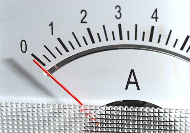
Image used courtesy of Adobe Stock
Because the deflection of a PMMC is directly proportional to the current through its coil, the instrument is essentially an ammeter. However, it can be employed directly as an ammeter only for the very small current levels that flow in the moving coil. Modifications must be made where an ammeter that measures larger currents is needed.
In the DC ammeter illustrated in Figure 1(a), a resistor known as a shunt is shown connected in parallel with the PMMC. Figure 1(b) shows the equivalent circuit of the complete instrument, including the coil resistance Rm and the shunt resistance RS. It is seen that a small portion of the current to be measured passes through the coil, and the rest passes through the shunt. From knowledge of the coil resistance and the meter full-scale deflection (FSD) current, the resistance of the shunt can be determined for any desired level of current to be measured. When the ammeter is designed to indicate a current of (for example) 100 A, the meter scale is recalibrated to read 100 A at FSD and proportional levels at other points.
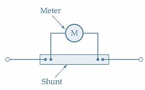
(a) The ammeter consists of a PMMC and a shunt
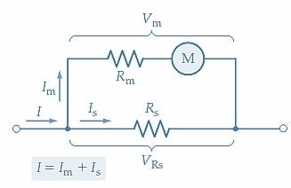
(b) Ammeter equivalent circuit
Figure 1. In an ammeter, a low-resistance shunt causes most of the circuit current to be bypassed around the low-current PMMC. The instrument measures a portion of the total current and indicates the total current on its scale. Image used courtesy of Amna Ahmad
The procedure for determining the shunt resistance value is demonstrated in Example 1.
Example 1
A PMMC has a coil resistance of 200 Ω and produces full-scale deflection when the coil current is 750 µA. Determine the shunt resistance value required for the instrument to function as an ammeter with an FSD = 1 A.
Solution
From Figure 1(b), the meter voltage is
\[V_{m}=I_{m}\times r_{m}\]
At full-scale deflection
\[V_{m}=I_{FSD}\times r_{m}=750\mu A\times200\Omega=150mV\]
The shunt voltage is
\[V_{s}=V_{m}=150mV\]
Shunt current
\[I_{s}=I-I_{m}=1A-750\mu A=999.25mA\]
And the shunt resistance is
\[R_{s}=\frac{V_{m}}{I_{s}}=\frac{150mV}{999.25mA}\approx0.15\Omega\]
Ammeter Resistance
It is important for an ammeter to have low resistance because it is always connected in series with the load to have its current measured. If the ammeter resistance is not significantly lower than the load resistance, including the ammeter in the circuit can lead to a substantial change in the load current, as illustrated by Figure 2 and Example 2.
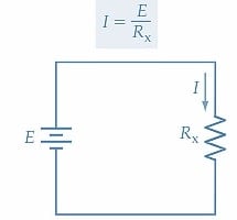
(a) Circuit without ammeter
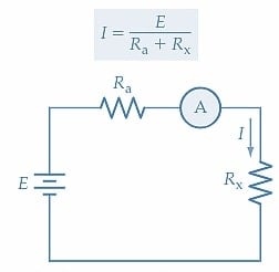
(c) Ammeter resistance adds to the circuit resistance
Figure 2. An ammeter should have a very low resistance so that it does not add significantly to the total resistance in a circuit and introduce an error in the measurement. Image used courtesy of Amna Ahmad
Example 2
An ammeter with a resistance of 1 Ω is to be used to measure the current supplied to a 4 Ω resistor from a 100 V source. Calculate the current through the resistor before the ammeter is connected and after it is included in the circuit.
Solution
Without the ammeter
\[I=\frac{E}{R_{x}}=\frac{100V}{4\Omega}=25A\]
With the ammeter in the circuit
\[I=\frac{E}{R_{x}+R_{a}}=\frac{100V}{4\Omega+1\Omega}=20A\]
Multirange Ammeters
A multirange ammeter can be constructed simply by using several shunt resistor values with a rotary switch to select the desired range. Figure 3(a) shows the circuit arrangement. When an instrument is used in this fashion, care must be taken to ensure that the shunt does not become open-circuited, even for a brief instant; otherwise, a very large current may flow through the coil of the instrument, possibly resulting in its destruction.
The make-before-break switch illustrated in Figure 3(b) protects a device from the possibility of the shunts becoming open-circuited in a multirange ammeter. The wide-ended moving contact connects to the terminal it is being switched to before it loses contact with the previous terminal. So, it makes contact with the next terminal before it breaks contact with the previous terminal. During the switching time, two shunts are in parallel with the instrument, and an open-circuited shunt is avoided.
(a) Multirange ammeter circuit
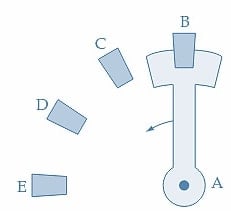
(b) Make-before-break switch
Figure 3. In a multirange ammeter, any one of several shunts can be selected. A make-before-break switch must always be used to keep the low-current PMMC shunted. Image used courtesy of Amna Ahmad
Ayrton Shunt
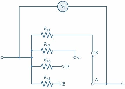
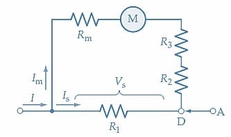
Because ammeter shunts have low resistance values, the switch contact resistances in parallel with the meter in the circuit shown in Figure 3 could introduce errors. The Ayrton shunt shown in Figure 4(a) avoids switch contact resistance in parallel with the meter and protects the moving coil meter from the possibility of excessive current flow. When the moving contact of the switch is connected to terminal B, the resistance of the shunt in parallel with the meter is (R1+R2+R3). This is illustrated in Figure 4(b). When the moving contact is switched to terminal C, the shunt becomes (R1+R2), and resistor R3 is now in series with the meter [Figure 4(c)]. Finally, with the moving contact at terminal D, the shunt is resistor R1, and (R2+R3) is in series with the meter [ Figure 4(d)]. Note that there is a shunt in parallel with the meter at all times and that the switch contact resistance is not part of the meter/shunt parallel combination. The shunt resistances are normally so much smaller than the low-current meter resistance that they have virtually no effect when directly in series with the meter.
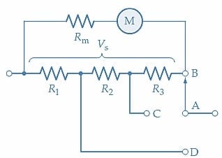
(a) Ayrton shunt and meter
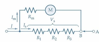
(b) Resistors R1+R2+R3 in parallel with the meter
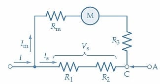
(c) R1+R2 in parallel with meter
(d) R1 in parallel with the meter
Figure 4. An Ayrton shunt has several series-connected shunts in parallel with the PMMC. By selecting a connecting point at one of the junctions of the shunts, one or more shunts can be placed in parallel with the PMMC circuit while the others are in series with the meter. Image used courtesy of Amna Ahmad
Analog DC Ammeter Takeaways
- Analog DC ammeters are instruments primarily used for measuring electrical current, with their deflection directly proportional to the current passing through their coils.
- To measure larger currents with a PMMC, a resistor called a shunt is connected in parallel, diverting most of the current away from the coil.
- The shunt resistance value can be determined based on the coil resistance and the desired full-scale deflection current.
- Low resistance is crucial for ammeters, as they are connected in series with the load being measured. High ammeter resistance can significantly alter the measured current.
- Multirange ammeters offer flexibility using various shunt resistor values with a rotary switch to select different current ranges.
- To prevent open-circuiting of shunts in multirange ammeters, a make-before-break switch is employed to ensure continuous shunting of the low-current PMMC instrument.
- The Ayrton shunt is an advanced solution that minimizes errors introduced by switch contact resistance in parallel with the meter. It allows for precise current measurement across multiple ranges.
Related Content