Facebook
 Google
 GitHub
 Linkedin
Basics of Capacitance
Learn about the unit of capacitance, explore capacitance parameters, and understand how capacitance behaves in series and parallel configurations.
Understanding the fundamental principles of capacitance is crucial in electronics and electrical engineering. Starting with the unit of capacitance, this article delves into the parameters influencing capacitance, including the effective plate area, the distance between plates, and the dielectric permittivity. Moreover, it sheds light on the behavior of capacitors when connected in series and parallel configurations, offering insights into their combined effects.
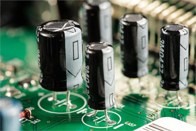
Image used courtesy of Adobe Stock
Capacitance represents the capacity of a capacitor to store electric charge. The size of a capacitor is known as the capacity. Within the automotive world, capacitors are often called condensers, referring to when capacitors were thought to “condense” electricity.
Unit of Capacitance
Capacitance is measured in Farads (F) and can be defined as representing the capacity of a capacitor that stores a one-coulomb charge at a voltage of one volt.
A coulomb represents the quantity of charge that traverses a point in one second when a current of one ampere flows.
Q = VC
and
Q = It
So
Q = VC = It
where
Q = charge in coulombs
V = voltage
C = capacity in farads
I = current in amperes
t = time in seconds
The Farad is very large, and submultiples are almost always used. The two most common submultiples of the Farad are:
Microfarads, 1 µF = 1E-6 F
Picofarads, 1 pF = 1E-12 F
The quantity of charge held in a capacitor depends on both capacitance, as defined above, and the voltage across the capacitor. The same charge can be stored in a large capacitor at low voltage and a small capacitor at high voltage.
Example 1
(A) A 10 µF capacitor is charged to a potential difference of 100 V. Calculate the charge.
\[Q=VC=100\times10E-6=100\times\frac{10}{1000000}=0.01\,C\]
(B) A 1000 µF capacitor is charged to a potential difference of 1 V. Calculate the charge.
\[Q=VC=1\times1000E-6=1\times\frac{1000}{1000000}=0.001\,C\]
Capacitance Parameters
The capacitance varies according to the following physical parameters:
1. The effective area of the plates. Capacitance, which is directly proportional to the effective area, is increased by increasing the number of plates (e.g., stacked plates) or the total area of the plates (e.g., rolled capacitors).
'Effective area' means the surface area adjacent to a plate of the opposite polarity. The outsides of the plates at either end of the stack do not count!
Electrolytic capacitors are etched to increase their surface area due to the bumps and hollows that are formed.
2. The distance between the plates. As the separation decreases, the electrostatic field strength increases, so more charge can be maintained, thus increasing the capacitance.
3. The permittivity of the dielectric. Capacitance is affected by the type of material used as the dielectric. For example, if the glass is used as the dielectric instead of air, the capacitance increases approximately six times. Glass also increases the capacitor's breakdown voltage considerably, so much higher voltages can be used.
The ratio by which the dielectric can increase the charge relative to air is called the 'dielectric constant.' The measure of the dielectric effect is known as 'permittivity.' Even a vacuum has permittivity, and the permittivity of a vacuum is known as the permittivity of free space or absolute permittivity.
A capacitor with two parallel plates has capacitance determined with the following equation:
\[C=\frac{\epsilon_{o}\epsilon_{r}}{d}\]
Where:
C = capacity in farads
εo = absolute permittivity (= 8.85E−12)
εr = relative permittivity
A = area of plates in square meters
d = distance between the plates in meters
The Farad is a very large unit, and to find a capacitor's value expressed in farads was at one time unheard of. Today, 2.5 V, 25 F super-capacitors, although rare, can be bought from electronics suppliers. The value of most electrolytic capacitors is normally expressed in microfarads, even when the figure is 10,000 microfarads.
The dielectric constant indicates how capacitance can be enhanced by substituting the air between the plates with a dielectric material. For example, if two parallel plates in the air had a capacitance of 120 pF and then the air was replaced with glass (the area and distance between the plates being unchanged), the capacitance would increase to 720 pF.
An insulating material with a high dielectric constant is used to increase capacitance without an increase in physical size.
The dielectric is made very thin to increase capacitance further or to reduce the physical size. However, if the voltage across the dielectric material is increased beyond the material's breakdown voltage, the insulation fails and becomes useless as an insulator between the plates. The same result occurs in variable capacitors if the voltage is kept constant and the thickness of the material is reduced.
The maximum voltage per unit thickness necessary to cause a dielectric breakdown through the material is referred to as the 'dielectric strength' of the insulating material, and selected values are shown in Table 1. The maximum voltage applied across a dielectric depends on the material type and its thickness.
Table 1. Dielectric Constants
|
Dielectric |
Dielectric constant (εr) |
Dielectric strength (kv/mm) |
|
Air/vacuum |
1 |
3 |
|
Paper |
2 |
40 |
|
Transformer oil |
4 |
15 |
|
Mica |
5 |
100 |
|
Glass |
6 |
30 |
|
Porcelain |
6 |
7 |
Capacitors In Series
When capacitors are connected in series, as shown in Figure 1, the effect is the same as adding the distances between the plates of each capacitor. The total distance between the plates is greater. Therefore, the total capacitance is less.
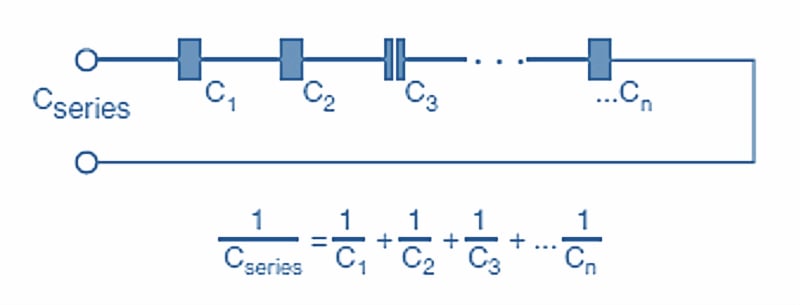
Figure 1. Capacitors in series. Image used courtesy of Amna Ahmad
The total series capacitance is found using the formula shown in Figure 1.
Example 2a
A 16 µF and an 8 µF capacitor are connected in series. Find the resulting capacitance.
\[\frac{1}{C_{total}}=\frac{1}{16}+\frac{1}{8}=0.0625+0.125=0.1875\]
\[C_{total}=5.3\,\mu F\]
To be more exact, the resultant capacitance in this example is 5.333 µF with a recurring decimal figure, but generally, capacitors can only be bought with a value of two significant figures.
If an applied voltage of 100 V were placed across these two capacitors in series, the charge in the whole circuit would be found by applying the formula Q = VC.
In this case, the overall quantity of charge is:
\[Q=VC=100\times5.33E-6=533E-6C\]
Again, remember that the same current flows for the same time in every component in a series circuit. The charge must be the same in each component. Since the capacity of each capacitor is different, the voltage across each capacitor will also be different. By transposing the formula Q = CV to V = Q/C, the voltages across each capacitor can be established.
It is important to note that the total capacitance in Example 2a, 5.3 µF, is less than that of either of the capacitors in the circuit. Also, the potential differences across the two capacitors must add up to the applied voltage according to Kirchhoff's Voltage Law.
Remember that, by Kirchhoff's Current Law, the current in each capacitor is the same as the total circuit current. Charge is dependent on current and time by the formula Q = It. Therefore, the charge in each capacitor and the whole circuit is the same; only the voltage across each capacitor changes.
Example 2b
Find the voltage across the 16 µF capacitor in example 2a.
\[V=\frac{Q}{C}=\frac{533E-6}{16E-6}\]
\[V_{C1}=33.31\,V\]
Repeating this for the voltage across the 8 µF capacitor results in:
\[V=\frac{Q}{C}=\frac{533E-6}{8E-6}\]
\[V_{C2}=66.625\,V\]
The total voltage would be:
\[V_{total}=V_{C1}+V_{C2}=33.31+66.625=99.935\,V\]
Kirchhoff's Voltage Law tells us that the sum of the individual voltage drops must add up to the total applied voltage, in this case, 99.935 V, a figure that compares well to the applied voltage of 100 V. If more decimal places were used throughout the calculations, the final figure would be even closer to 100 V.
Capacitors, therefore, have to be selected not only by capacity but also by the voltages expected to exist across them, that is, their working voltages.
Where the capacitors in series are of equal capacitance, the potential differences will be divided equally between them. Importantly, from Ohm's Law, if one capacitor becomes short-circuited, other capacitors in series will be subjected to higher-than-normal voltages.
Capacitors In Parallel
Placing two or more capacitors in parallel is the same as increasing the area of the plates. As each capacitor is added in parallel, the effective capacitance of the group is raised as if by adding more area. The dimensions do not matter, but calculating parallel capacitors is easy—simply add them up. The total capacitance in a parallel circuit is the sum of the individual capacitances, as shown in Figure 2.
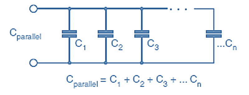
Figure 2. Capacitors in parallel. Image used courtesy of Amna Ahmad
Capacitors in parallel are subject to the same rules as other components in parallel circuits. They have the same voltage across them. Since the voltage is the same across each capacitance, the total charge can be calculated from the capacitances and the applied voltage.
Example 3
A 4 µF and an 8 µF capacitor are connected in parallel across a 100 VDC supply. Find “a” ( total capacitance), “b” and “c” (the charge on each capacitor), and “d” (total charge).
a. The total capacitance is found as follows:
\[C_{total}=C_{1}+C_{2}=4\mu F+8\mu F=12\mu F\]
b. For the 4 µF capacitor, the charge will be found from Q = VC, that is:
\[Q_{C1}=4E-6\times1000=4E-4\,Coulumbs\]
c. Similarly, for the 8 µF capacitor:
\[Q_{C2}=8E-6\times1000=8E-4\,Coulumbs\]
d. The total charge is found by addition, that is:
\[Q_{total}=Q_{C1}+Q_{C2}=4E-4+8E-4=1.2E-3\]
Takeaways of Capacitor Basics
As an electrical engineer, it is crucial to understand the basics of capacitors as a power electronics component. Farads represent the ability of a capacitor to store charge per unit of voltage. The effective area of plates, the distance between plates, and dielectric permittivity are key factors influencing capacitance. Increasing plate area or decreasing plate separation boosts capacitance, while a higher permittivity dielectric enhances it further. Capacitors connected in series result in reduced overall capacitance, whereas in parallel, capacitances sum up. For instance, when a 2μF capacitor and a 3μF capacitor are connected in series, the total capacitance decreases to 1.2μF. Conversely, in parallel, their combined capacitance would be 5μF.