Facebook
 Google
 GitHub
 Linkedin
Intelligent Power Modules Utilizing BJTs, MOSFETs, and IGBTs
An intelligent power module (IPM) is a power semiconductor module that integrates into a single package all the circuitry required to operate an IGBT. It includes the required drive circuitry and the protection functions, as well as the IGBTs. In this way, the best possible performance can be achieved from an available IGBT technology. Overcurrent, overheating, and under-voltage detection are three of the self-protection functions commonly found in an IPM. In this article, we’ll look at some of the basic concepts of this technology and see how an IPM can extract the best performance possible from an available IGBT device.
Power BJTs, MOSFETs, and IGBTs
Power BJTs have desirable on-state conduction performance; however, they are current-controlled devices and need complex base drive circuitry. With power MOSFETs being voltage-controlled devices, we need simpler drive circuitry. However, the major challenge with power MOSFETs is that their on-state resistance increases with device breakdown voltage. At voltage ratings above 200 V, MOSFETs exhibit inferior conduction performance as compared to a BJT.
An IGBT combines the best of these two worlds to realize a high-performance power switch: it offers the ease of drive of a MOSFET with on-state characteristics of a BJT. The main problem with an IGBT is a parasitic PNPN (thyristor) structure that can lead to device failure. Figure 1 illustrates the creation of this parasitic thyristor.

Figure 1. Vertical cross-section and an equivalent circuit model of a punch-through (PT) IGBT. Image courtesy of STMicroelectronics.
Depending on the current density and the rate of change of voltage (dvdt) at the device turn-off, the parasitic thyristor can turn on and cause device failure (latch-up). In this case, the IGBT current is no longer controlled by the gate voltage. The latch-up current is shown in Figure 2.

Figure 2. Latch-up current. Image courtesy of STMicroelectronics.
Note that the body region resistance and the gain of BJTs are functions of ambient temperature and the device becomes more susceptible to latch-up at elevated temperatures.
The Basic Concept of an Intelligent Power Module (IPM)
Over the years, the IGBT manufacturers have improved the device physics to achieve better power switches that are capable of withstanding relatively larger current densities without experiencing a latch-up failure.
Instead of optimizing the device performance, some manufacturers decided to add some control circuitry to the available IGBTs to prevent it from latch-up. This control circuitry, which is integrated with the IGBT, is a feedback loop with current sensing capability. It monitors the device's current density to shut the device down when an overcurrent/short-circuit condition occurs. This feedback mechanism leads to an “intelligent” power switch that can protect itself from failure conditions. This basic functionality of an IPM is illustrated in Figure 3.

Figure 3. Basic functionality of an IPM. Image courtesy of Wiley InterScience.
Current Sensing Methods
IPMs employ several different ways of sensing the IGBT current. Some IPMs pass the IGBT current through an external shunt resistor to create a voltage proportional to the device current. The IC compares this voltage with a preset threshold value to detect an overcurrent condition. Figure 4 shows a simplified block diagram of the DIPIPM which is based on a shunt current sensing resistor. In this case, the voltage across RSHUNT is sensed and low-pass filtered before being monitored by the CIN pin of the IC.

Figure 4. Simplified block diagram of the DIPIPM. Image courtesy of Powerex.
Another technique of overcurrent detection is called desaturation detection, which is based on monitoring the IGBT collector voltage. During normal operation, the collector-emitter voltage of the IGBT is very low (1 V to 4 V typically). However, in the event of a short-circuit, the IGBT collector-emitter voltage increases. Therefore, this voltage can be used to detect an overcurrent condition.
A disadvantage of the desaturation method is that it usually allows a high dissipation in the IGBT while detecting a short circuit condition.
Soft Shutdown of the IGBT
The feedback loop that monitors the device current should be able to detect the overcurrent condition rapidly. However, it is desired to shut down the IGBT slowly after overcurrent is detected. Such a soft shutdown is implemented to suppress destructive surge voltages. The paper mentioned above discusses that a soft shutdown can reduce collector-to-emitter peak voltage by 30% when turning off a short-circuit collector current of 260 A.
Other Common Features
IPMs include other self-protection functions in addition to the short-circuit detection discussed above. Over-temperature and under-voltage protections are two of these functions that are commonly found in IPMs.
The under-voltage function monitors the power supply of the control circuitry of the IPM for an out-of-tolerance condition. When the supply voltage crosses a preset threshold value, the under-voltage function turns off the power devices. This is done to avoid operating the IGBTs in the active (or linear) mode of operation that can be catastrophic.
The over-temperature function turns off the power devices when the chip temperature goes above a threshold temperature.
Packaging
Advanced packaging is the key to building high-performance IPMs that need to implement the gate driver, sensing logic, and power semiconductor within the same hybrid IC package. Being notably different from a monolithic IC, a hybrid IC places individual components such as transistors, monolithic ICs, resistors, inductors, and capacitors in a single package. These components are bonded to a substrate or printed circuit board (PCB) inside the package.

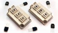
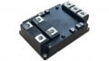
Figure 5. The internal components required for an IPM. Image courtesy of ON Semiconductor.
IPMs are used for voltage ratings up to 600 V from a current rating as high as 100 A. As the power levels increase, the package heat extraction capability becomes more and more important. The substrate of a power module commonly operates at a temperature of 150-200 °C. Therefore, the substrate should exhibit high thermal conductivity so that we can place high power components in close proximity within a compact package. This is why new materials and advanced packaging technologies can significantly affect the size, weight, and performance of power semiconductor modules.
A Review of IPMs
The IPM IC incorporates a built-in drive circuitry to achieve the best performance possible from available IGBT devices.
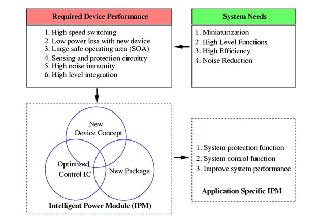
Figure 6. The key concepts of IPMs and ASIPMs. Image courtesy of Jong Mun Park.
IPMs have several self-protection functions such as overcurrent, overheating, and under-voltage detection. We saw that modern IPMs require high-performance power switches, optimized control circuitry, and advanced packaging technologies.