Facebook
 Google
 GitHub
 Linkedin
InDUR Nonlinear and SiFe – Special AC Filter and DC Power Inductors
This article discusses the new applications of the thermally optimized STS InDUR inductors are presented and offers method to optimize the inductance curve.
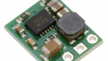
In many power electronics topologies, a certain drop of the choke’s inductance can be accepted at higher current levels which offers the opportunity of smaller passive components. To achieve optimum designs, the inductors have to meet the specified L(I)-curve as close as possible. In this article, new applications of the thermally optimized STS InDUR inductors (Figure 1) [1][2] are presented. Therein, state-of-the-art powder materials (e.g. like Sendust and combinations with other materials) are utilized to optimize the inductance curve. Furthermore, standard silicon iron steel (SiFe) can be applied to achieve cost-effective constructions in the frequency range between 1kHz and 10kHz. Finally, all these practical solutions are compared with each other regarding power density, efficiency and weight.

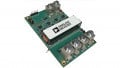
Figure 1: Optimized inductors for 3m/s forced air cooling (a) and cold plate mounting (b)
Figure 2 depicts the typical current shapes of Buck-Boost-converters and 50/60Hz AC filtering. It is indicated that the ripple current is increased at higher current levels in both cases. Due to the voltage-controlled systems, this is equivalent with lower inductance at higher power. In Figure 3, the desired characteristic is given by the specification (crosses).

Figure 2: Current shapes of Buck-/Boost-converters (a) and 50/60Hz AC filtering (b)
To give a comparison, different example inductors were realized based on the specification. Figure 3 shows the resulting L(I)-curves for different core materials. Besides the specified values of the (differential) inductance L (I‹0)≤ 240 µH, L(I=220A)≤170µH and L(I=370A)≤110µH, a nominal DC current of 193ADC, a switching frequency of 10kHz and forced air cooling with 3m/s airspeed have to be considered. Due to the decrease of the inductance, the ripple current increases at higher power: IPP={35APP, 50APP, 77APP} at {0ADC, 139ADC, 330ADC}.
Comparing the different results in Figure 3, it is obvious that linear core materials like conventional ferrite or silicon iron steel will never lead to optimum designs.

Figure 3: Specification and L(I)-curves of the example inductors realized with different core materials
This is due to the fact that these inductors have to be strongly oversized to keep the specified inductance at maximum current. Consequently, these inductors can store much more energy at lower power than required [3]. Below, these dependencies are explained in detail.
STS’s Modular Core Concept
To adapt the curve to the specification as close as possible, STS has the opportunity to apply different nonlinear core materials like Sendust and combinations with other materials in a modular core concept consisting of block yokes and cylindrical discs for the legs. Furthermore, spacers of different height can be included to realize a distributed air gap.
This allows an optimum adaptation of the magnetic circuit and finally reduces the eddy current losses due to the air gap fringing fields to the minimum.
Now a 2D-FEM simulation is conducted to verify the expected inductance value. Figure 4 shows the solution of the magnetic flux density distribution inside the choke (material mix of Sendust and other materials). It has to be mentioned that the air gap length had to be slightly adapted in 2D to meet the exact value of the no-load inductance. This is due to the fact that the fringing flux of the air gaps is a little bit different in reality respectively in 3D. After that, the complete L(I)-curve was simulated to see that the specification is kept. However, the differential L(I)-curve is needed while a magnetostatic model was built with an FEM-Simulation program. Therefore, the differential inductance curve had to be derived from φ(I) in post-processing by L=δφ(I)/δI.
![Magnetic flux density |B(x,y)| [T] (I=193A, Sendust with other material)](https://eepower.com/uploads/thumbnails/STS_Spezial_Fig_4.jpg)
Figure 4: Magnetic flux density |B(x,y)| [T] (I=193A, Sendust with other material)

Table 1: Comparison between the different inductor solutions
Comparing the optimized solutions for ferrite and silicon iron steel in Figure 5a, it can be seen that the ferrite inductor can carry much more total flux for currents beyond the specification (450A and 800A.). The orange area is equivalent to the flux-difference. This is due to the fact that the ferrite yokes are slightly oversized in comparison to the SiFe yokes — these run into full saturation simultaneously with the leg discs. The purple area in Figure 5b symbolizes the Δφ by which the SiFe inductor has to be oversized in comparison to the powder inductor that gives the optimum adaptation to the magnetic problem here.

Figure 5: L(I) magnetization curves with areas that indicate different flux-portions
Conclusions
For a short conclusion, all relevant technical data of the example inductors are listed in Table 1. The described solution of the powder inductor (Sendust and other material) represents the optimum solution regarding power density, efficiency and weight. As in many other cases, the smallest component gives also the most efficient one here. All comparison was made on the basis of a constant hot-spot temperature (here 140°C). It has to be mentioned that the winding gives the hot-spot of the ferrite and the powder inductors (high current density, low core losses). In case of the SiFe inductor, the hot-spot is inside the core (low current density, high core losses). The magnetization curve of the optimized powder inductor is finally depicted by Figure 6.

Figure 6: L(I) magnetization curve of the optimized inductor (Iron Powder Mix)
References
- A. Stadler, C. Gulden, “InDUR — New Power Inductors with Minimum Size and Weight for DC and AC Filter Applications”, Bodo’s Power Systems Magazine, January 2014, pp. 36-38
- S. Herzog, A. Stadler, C. Gulden, “MaxFlux – Magnetically biased inductor”,
- Bodo’s Power Systems Magazine, June 2014, pp. 30-34
- A. Stadler, C. Gulden, “Efficient nonlinear inductors for PV inverters and active PFC”, 7th International Conference on Integrated Power Electronics Systems CIPS, March 2012, Nuremberg, Germany
About STS
STS stands for the development and production of power transformers and power chokes. Our success is based on customer-specific inductive components in the medium frequency range for applications in the business units of industrial, medical, railway and renewable energies.
This article originally appeared in the Bodo’s Power Systems magazine.