Facebook
 Google
 GitHub
 Linkedin
How SiC MOSFETS are Made and How They Work Best
This article highlights Avnet Silica devices featuring STSiC Power components for SiC information.
Semiconductors came a long way since the early beginning of the minute man project and the traitorous eight puzzling about if better office air filtering would increase the yield of their production. In the more recent years there has been a big push into energy efficient conversion.
With this push, silicon MOSFET’s with RDSon values in the low mΩ range became a familiar thing for low voltage devices, but the higher the blocking voltage of MOSFET’s go, the higher the RDSon gets. With such high RDSon, these devices were still unsuitable for high voltage and high power applications and the only way to handle such applications were the use of IGBT devices. Silicon Carbide or in short SiC has proven to be a material with which it is possible to build MOSFET like components that enable circuits with even more efficiency than it has ever been possible with IGBT’s before. SiC gains a lot attention these days, not only because of its properties but also because the devices get more and more price competitive to IGBT’s and manufacturers bring in a long term investment strategy, at system level, to secure supplies.
STPOWER portfolio
One of the manufacturers that made its way on to the top of SiC suppliers is without a doubt STMicroelectronics. STMicroelectronics invested a lot in research and development in past years to get a comprehensive STPOWER portfolio for the market, but there were also significant invests in the supply of the material. In 2019 STMicroelectronics acquired the Swedish SiC manufacturer Norstel AB, also did a multi-year agreement with CREE and later in early 2020 with SiCrystal, a Rohm subsidiary, too on SiC wafer supply just to name some strategic movements that have been made.This strategy proves itself very well for STMicroelectronics and so they became a key player in the very fast growing SiC market. To not just water your mouth, now lets discuss SiC devices.
Silicon Carbide, The Not So New Material
The very first documented experiments with SiC material were around 1849 and the material is already widely in use in bullet proof vests or as abrasive. One of the inventors of the IGBT discussed in [1] back in 1993 the superior behaviour of different SiC material compared to Silicon (Si) devices. Table 1 shows values of the different materials that have been discussed in [1] and [2]. These values make some interesting statements about SiC materials. The breakdown electric field strength Ec is more than a magnitude better than Si at a doping level of 4:8x1016cm-3.
The higher saturation drift velocity vSAT as well as the higher bandgap voltage Eg also stand out. An interesting figure is λ which states the thermal conductivity. Here SiC materials are more than twice as good as Si, which brings new possibilities to packaging and packaging density as well as current handling capability. However, [1] is from 1993 and just in the last few years SiC was gaining traction in the market, so there must have been some roadblocks that had to be solved. On of the roadblocks was an appropriate bulk growing process. With Si the bulk growth according to the Czochralski process is well understood and established. The usual growth rate of such a bulk is several meters per hour.
This process however is not suitable for SiC bulk growth. For SiC production a process called physical vapour transport (PVT) has to be used. This process uses a crystal seed on top of a chamber and beneath it there is SiC source material that gets heaten up to around 2000 - 2500°C. This high temperature causes vapour to rise from the source material to the crystal seed and so the bulk grows. This process unfortunately is not as fast as the Czochralski process and so the resulting growth speed is several millimeters per hour which is a lot slower than Si growing. Unfortunately the process still is far from perfect and there is a relatively high density of defects within the material which is described in detail in [2].
| Si | 6H-SiC | 4H-SiC | GaN | |
| Eg [eV ] | 1.1 | 2.86 | 3.26 | 3.45 |
| vSAT [cm/s ] | 107 | 2x10⁷ | 2.2x10⁷ | 2.2x10⁷ |
| Ec | 2x10⁵ | ˜4x10⁶ | ˜3.2x10⁶ | ˜3x10⁶ |
| λ [ W/cmdegC ] | 1.5 | 4.9 | 4.9 | 1.3 |
Table 1: Comparison of Si to 6H-SiC,
In table 1 there is also GaN referenced with its material properties. This material and its resulting products are also causing some stir in the market at the moment, but at the moment the market traction is not as big as it is for SiC and the focus is more on devices around and below 600V in high frequency applications. There is certainly a place for such products but the product variety as it is there for SiC isn’t there at the time this article is written and semiconductor vendors focus more on SiC than they do for GaN. This is also due to the reason that the process of SiC is in lots of points very similar to Si process and machines can be used for both materials which is clearly an advantage.
Device Properties And Their Gate Driving
Now that we have elaborated on the SiC material properties and learned, that it is superior in its parameters compared to Si in high energy applications it is time to look closer into the devices and applications. As introduced above, STMicroelectronics is one of the top players in the SiC market, so lets have a look at their product portfolio in figure 1.
When looking at the voltage range the portfolio addresses it is clear that there is a range where SiC MOSFETs compete with Si MOSFETs and there is a range where they compete with IGBT’s. In the lower voltage range Si MOSFETs do come quite close with the SiC devices but, SiC devices can offer a lower gate charge and a better thermal specification. The other end of the spectrum are the IGBT devices. Here it is clear that due to the low RDSon of a SiC MOSFET these devices are unquestionable superior to IGBT’s, not mentioning the, again, lower gate charge.
When switching off SiC MOSFET’s with 0V, one effect has to be considered, the Miller effect which is already known from Si MOSFET’s. This effect can be problematic when the device is used in a bridge configuration, especially when one SiC MOSFET is switched on and the second experiences a surge on its Drain and switches on accidental due to parasitics. This turn on creates a short circuit from high voltage to ground and consequently damages the circuit.

Figure 1: Product placement of SiC Power MOSFETs in the ST portfolio, STPOWER
How to Drive SiC MOSFETS
With the superior material properties in mind the question poses how these parts have to be controlled on to work at their very best. Starting from things we know, Si MOSFETs need a positive gate voltage, which is recommended around 12V or even less and the negative gate voltage should be ground potential. IGBT’s have an asymmetrical gate driving voltage, that means that the positive gate voltage is around 15V and the negative voltage is around -5V .

Figure 2: SCT30N120 output characteristics (Tj = 25 °C)
A SiC MOSFET basically works with the voltage levels of a Si MOSFET or IGBT, but not at its best parameters. Ideally a SiC MOSFET gets at its gate 20V for being switched on at the minimum RDSon.
When switching off SiC MOSFET’s with 0V, one effect has to be considered, the Miller effect which is already known from Si MOSFET’s. This effect can be problematic when the device is used in a bridge configuration, especially when one SiC MOSFET is switched on and the second experiences a surge on its Drain and switches on accidental due to parasitics. This turn on creates a short circuit from high voltage to ground and consequently damages the circuit.
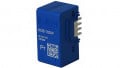
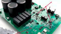
However SiC devices can be operated at lower gate voltages than the 20V named earlier, but the output characteristics change a lot, as it can be seen in figure 2. It can be concluded that a lower gate voltage results in a lower overall system efficiency. Optimizing the SiC MOSFET gate driving circuit for low RDSon with high enough gate voltage is just half of the work that can be done to optimize for losses. Switching losses are the other part that can be optimized, like showcased in [3]. For driving the SiC MOSFETs in [3] STGAPxx MOSFET drivers have been used. STGAPxx MOSFET drivers do come in two different flavours as can be seen in figure 3 and figure 4. In figure 3 the schematic shows how gate driving of SiC MOSFETs can be done when using a bipolar gate driver supply. This bipolar gate driving voltage is not mandatory as described above but it helps to minimize the Miller effect and creates a better controllable on and off switching. Figure 4 therefore shows a schematic with an active Miller clamp. This enables the designer to have a unipolar gate driver supply.

Figure 3: STGAP2SICS with a half bridge configuration and separate gate driving paths.

Figure 4: STGAP2SICS with a half bridge configuration and a combined gate driving path with additional miller clamp.
Taken out of [3] figure 5 and 6 show the difference it makes when optimizing the resistors in the gate driving circuit in terms of energy losses. The difference between having a 10Ω or a 1Ω is 250μJ in losses that can be eliminated. It also points out that the switching losses are not symmetrical that means for switching on losses are different to switching off. Also worth noting that in case a longer switch off time is needed for better EMI performance it does not hit the efficiency as hard as it does for switching on because the slope is lower.
And there is one more thing to point out when comparing IGBT with SiC. A major difference from SiC MOSFET’s to IGBT’s is, when the devices are switched off. To be completely switched off, the IGBT needs to sweep out its minority carriers completely. This last transport happens when the IGBT is already switched off and the voltage across the collector and the emitter is at its maximum and so it has a huge contribution to the switching losses of an IGBT. This effect, called tail current, does not exist with SiC MOSFETs and switching off can be done with less energy losses.
Conclusion
The parameters and properties that have been discussed in this article shine a light on certain aspects when doing power electronic designs. Current and future electronic designs such as battery charger, motor and solar inverter can hugely benefit from these new devices not only in efficiency but also in size enabling high-power, high-temperature operation. But it is not only the device’s properties that make curious for new designs and the future its also the strategy of STMicroelectronics. Silicon Carbide (SiC) technology is part of strategy at STMicroelectronics, STPOWER, to invest in wide bandgap (WBG) technologies, which also include Gallium Nitride (GaN). The company dedicated a huge amount of resources to this technology, which promises a bright future and even better performing SiC devices which we all can be curious about and looking forward to.
![Figure 5: Eoff vs. Rg at VDD=800 V, ID=20 A, VGS=-2 V to 20 V, Tj=25 °C as been tested and calculated in [3]](https://eepower.com/uploads/articles/How_SiC_MOSFETS_are_Made_and_How_They_Work_Best_Fig5.JPG)
Figure 5: Eoff vs. Rg at VDD=800 V, ID=20 A, VGS=-2 V to 20 V, Tj=25 °C as been tested and calculated in [3]
![Figure 6: Eon vs. Rg at VDD=800 V, ID=20 A, VGS=-2 V to 20 V, Tj=25 °C as been tested and calculated in [3]](https://eepower.com/uploads/articles/How_SiC_MOSFETS_are_Made_and_How_They_Work_Best_Fig6.JPG)
Figure 6: Eon vs. Rg at VDD=800 V, ID=20 A, VGS=-2 V to 20 V, Tj=25 °C as been tested and calculated in [3]
References
[1] Mohit Bhatnagar and B Jayant Baliga. “Comparison of 6H-SiC, 3CSiC, and Si for power devices”. In: IEEE Transactions on electron devices 40.3 (1993), pp. 645–655.
[2] Gernot Gruber. “Performance and Reliability Limiting Point Defects in SiC Power Devices”. Dissertation. Technical University Graz, 2016. URL link.
[3] G. Catalisano L. Abbatelli C. Brusca. AN4671 - How to fine tune your SiC MOSFET gate driver to minimize losses. manual. 2015. URL link.
This article originally appeared in Bodo’s Power Systems magazine.
About the Author
Thomas Hauer worked as a Power/High Power FAE at Avnet Silica that is a semiconductor distributor that offers creative solutions, technology and logistics support.