Facebook
 Google
 GitHub
 Linkedin
High Performance 1 kW per Phase 48 V/12 V Converter Using GaN ePower Stage
How integrated GaN technology drives superior performance, simpler design, and reduced cost in 48 V/12 V automotive mild hybrid applications.
Introduction
Automotive 48 V/12 V converters are essential in modern hybrid electric vehicles, as the energy is exchanged between the 48 V and 12 V buses. This two-voltage system accommodates legacy 12 V systems and provides higher power for 48V to loads such as vacuum and water pumps, electric super chargers, steering, and audio systems. Among all the requirements for the 48 V/12 V converter, efficiency, power density, size and cost are on the top of the list. This article addresses these design criteria by employing the GaN ePower Stage, EPC23101, and compares it with a previous design using discrete EPC2206 devices.
GaN ePower Stage Chipset
GaN FETs used in 48 V applications are rated between 80 V and 100 V, and usually have a 4 times better figure of merit (ADie ·RDSon) compared to equivalent MOSFETs [1]. For the same gate voltage of 5 V, GaN FETs have at least 5 times lower gate charge than equivalent MOSFETs. Other important advantages of GaN FETs include lower COSS, faster voltage transition, zero reverse recovery QRR and are physically smaller.
Monolithic integration of GaN power FET and gate drivers has already been established [2], but with limited power ratings, mainly due to die size. To accommodate applications with high power and also provide more design flexibility, the new EPC23101 integrates only the upper GaN FET of a half bridge with a complete half bridge gate driver, as shown in Figure 1.

Figure 1. EPC23101 concept diagram. Image used courtesy of Bodo’s Power Systems
The on-resistance of the integrated power FET is 3.3 mΩ, with a maximum voltage and current rating of 100 V and 65 A respectively. The gate driver can be supplied with 5 V and the PWM inputs can accept 3V3 logic levels. In addition, the EPC23101 includes an enable pin allowing the gate driver to be placed in low quiescent power mode when disabled. It is available in an exposed-top QFN package that measures 3.5 mm by 5.0 mm with solder bars that comply with IPC-2221 creepage and clearance requirements for its rated voltage.
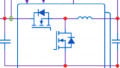
To form a half bridge, an external low side GaN FET is required. The EPC2302 is the good choice for this example application. The EPC2302 is a 100 V rated 1.8 mΩ device that is available in a similar QFN package as the EPC23101. This asymmetrical half bridge yields an optimal balance between switching and conduction losses for 48 V/12 V converter [3]. A photo of this chipset (EPC23101 and EPC2302) and a functional block diagram is shown in Figure 2.

Figure 2. Photo of EPC23101 and EPC2302 chipset with functional block diagram. Image used courtesy of Bodo’s Power Systems
Converter Design
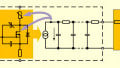
A 2-phase synchronous buck converter topology was selected for the demonstration of the ePower stage technology. This converter can also operate as a boost in reverse. A simplified schematic diagram is shown in Figure 3 that includes the power stage and support functions such as current sensors, temperature sensor, digital controller and 5 V and 3.3 V auxiliary power. Each phase is designed to carry up to 70 A current on the 12 V bus. This equates to 1 kW at 14.3 V. The total maximum output power of this design is 2 kW, or 140 A into the 12 V bus. Furthermore, the design is scalable, so two boards can be paralleled for a 4 kW system.

Figure 3. Simplified schematic diagram. Image used courtesy of Bodo’s Power Systems
The PCB layout of the power stage plays a critical role. Parasitic inductance can affect efficiency and voltage overshoot. A good layout contributes to high reliability. This design utilizes the internal vertical layout technique [1] to minimize parasitic inductance by placing the decoupling capacitors close to the FETs with a solid ground plane beneath. Symmetrical layout between the two phases is also important for current balancing and minimizing the effects from mismatch, such as switching transition, overshoot, etc.
Compared to the design using discrete EPC2206 [4], the layout with GaN ePower stage chipset is much simpler, as shown in Figure 4. The majority of the gate driver components on the bottom side of the PCB is eliminated. This results in a reduction of the occupied area from approximately 1.5 cm2 to 0.9 cm2, or 40%.
There is limited selection for off-the-shelf high-current automotive grade inductors. This design uses the 1 µH inductor with 65A saturation current rating from Vishay IHTH-1125KZ-5A series.

Figure 4. Layout comparison of discrete GaN FET with gate driver and integrated ePower stage chipset. Image used courtesy of Bodo’s Power Systems
To ensure accurate phase-current balancing, current sensing using a precision shunt resistor is used, together with digital average current mode control and an active current balancing algorithm. Using a Microchip dSPIC microcontroller with high resolution PWM (250 ps), the inner current loop bandwidth is set to 8 kHz, and the voltage loop to 800 Hz.
Performance Evaluation
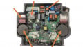
Figure 5 shows a photo of the converter (EPC9170). With the heatsink installed and 2000 LFM airflow, the converter was operated at 48 V input, 14.3 V output and 500 kHz switching frequency. The measured efficiency is shown in Figure 6, compared with the converter built with discrete EPC2206 and external gate driver [4]. By using integrated solution, this converter achieved higher peak efficiency, at 96.7%, and also higher full load power. At full load of 1 kW/phase, the efficiency is 95.8%. With the reduced occupied area, this also leads to higher power density.

Figure 5. Photo of the EPC9170 with EPC23101 and EPC2302 ePower stage chipset. Image used courtesy of Bodo’s Power Systems

Figure 6. Measured efficiency of EPC9170 (integrated EPC23101 and EPC2302) compared with discrete EPC2206. Image used courtesy of Bodo’s Power Systems
Conclusion
GaN FETs have demonstrated superior performance in automotive 48 V/12 V applications over equivalent MOSFETs. With the integrated ePower stage chipset of EPC23101 and EPC2302, designers can further improve the converter performance, while reducing size and cost through reduced component count. This design example used the chipset in a 2-phase synchronous buck converter and demonstrated significant performance gain compared to the previous design using discrete EPC2206, achieving peak efficiency of 96.7% and full load efficiency of 95.8% at 2 kW, when converting 48 V to 14.3 V and switching at 500 kHz.
This article originally appeared in Bodo’s Power Systems magazine.
Related Content