Facebook
 Google
 GitHub
 Linkedin
Heat Dissipation Challenge in Automotive High-Power Integrated Magnetics
This article highlights PREMO Group launched the 3DPower™ as the first product to integrate two magnetic components that share the same core.
In 2016, Premo Group launched 3DPower™, the first product to integrate two magnetic components that share the same core and feature two orthogonal magnetic fields at all points within the core. As a result, the increased power density in the component makes heat dissipation a tough challenge for our designers.
This article focuses on discussing the advances achieved by PREMO regarding heat dissipation techniques in 3DPower. The biggest impact of magnetic integration is volume reduction when compared to a discrete solution for the same component. A consequence of increasing the power density is a temperature rise of the part.
Thermal Management & 3DPower
3DPower Pot-Core uses a custom pot-core shape where 2 inductive components are integrated. One of them is placed in the pot-core itself and the other one outside the pot-core as if it were a toroid. This product allows us to solve the engineering challenge of integrating magnetics: in this case, it consists of a choke and a transformer. Unlike other magnetic integration technologies, both components share the whole core volume in the 3DPower. For this purpose, the magnetic field of one component is orthogonal to the other, resulting in 2 independent and fully uncoupled magnetic elements.
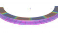
As seen in Figure 1, there is one winding inside the ferrite core (70a) while the other orthogonal winding is outside (70b/c/d). Designers of magnetics for mass production know that ferrite cores break easily, particularly when the winding is machine-made. Hence, it was necessary to cover the core with a coil. Imagine how hot a core can be when it contains a winding with a few tens of amps, and it is covered by a plastic coil that has also wired around it. Plus, this results with the core self-heating due to core losses.

Figure 1: Pot-core solution (left); detailed cross-section (right).
Most of the times overheating failures are caused not only by the overall temperature increase but also by hot spots. Hot spots can create temperature gradients in the ferrite core that could lead to breaks or poor performance. Therefore, the main goal is to avoid hot spots by creating a good thermal link between all the components, ensuring a proper cooling system to remove heat.
Premo can provide fully customized solutions of the 3DPower. However, due to its geometry, the main applications are Phase-Shifted Full-Bridge and Resonant LLC DC/DC converters. The output power range spans from 1 kW to 11 kW, but higher powers can be reached on demand. One of our latest developments can be seen in Figure 2, where three magnetic components are combined in one single core (1 transformer and 2 inductors). This is just one example of how easy is to integrate magnetics by using our innovative technology.

Figure 2: Step-down transformer + series inductor + parallel inductor for a 3.5kW LLC converter.
Thermal Link
A proper design and wide selection of materials are key for successful thermal performance. The image below shows an 11kW transformer where windings were made using stereolithography 3D printing technology and cooled with water in the bottom core. The wire is much hotter than the core, particularly on the bottom.
The solution consists of using thermal conductive plastics on the coils to create a thermal link between the wire and the core, for example with a thermal pad or thermal liquid gap filling material. In the 3DPower, thermal liquid gap filler was dispensed to guarantee a reliable thermal link between the coils, windings, and core.
Core Adhesive
Core sets are supplied in halves. The easiest and most inexpensive way to join two cores is to use tape, which is common for economical and small transformers. Although the magnetic path is not affected, the thermal resistance is high between the two cores. Thus, when one of the cores is attached to a heatsink, the temperature gradient in the other one is so high that it could lead to ferrite breaks.

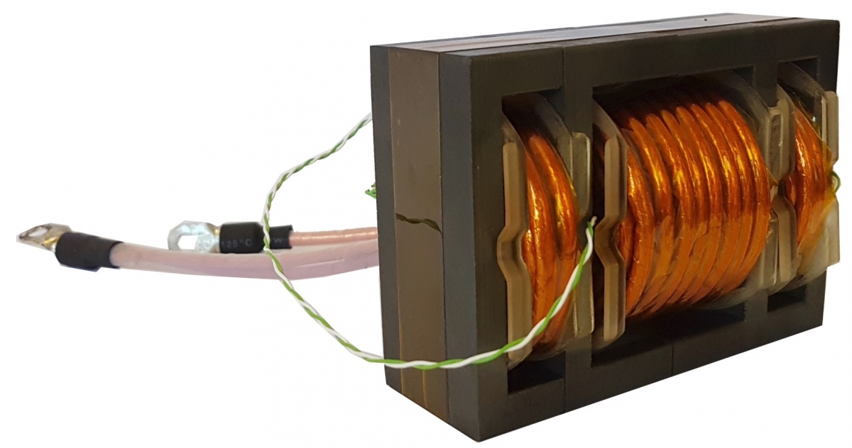
Figure 3: IR image of an 11kW transformer with load. Overview of the 11kW transformer.

Figure 4: Temperature gradient of core sets with different adhesives: standard adhesive (top), high thermal conductive adhesive (bottom).
We performed tests in our R&D facilities and the results highlighted that when using a standard adhesive, the gradient of temperature between the two cores halves is twice than when using a high thermal conductive adhesive. The ferrite not only breaks but, due to an inductance variation with temperature, the reluctance of both cores will be different and can create an undesirable performance.
Coil Plastics
As explained, the pot core is covered with a plastic coil to protect the ferrite during the winding process and to provide electrical isolation. This coil will be exposed to the air if natural or forced convection is used. It is also exposed to a cooling plate if water cooling is used instead.
Three different plastics were tested for natural convection. The first plastic was a commonly used Liquid-Crystal Polymer (LCP) ~0.5 W/m·K thermal conductivity, the second one was a PA6-based compound (polyamide) with 1.2W/m·K thermal conductivity, while the third one was also a PA6-based plastic with 4W/m·K thermal conductivity. The three samples were prepared with thermocouples inside and tested at the same operating point. The temperature measurements were logged and fitted according to the method of least squares (Equation 1). This equation simplifies the thermal model, which becomes a lumped capacitance model.
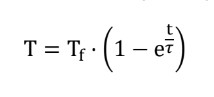
Equation 1
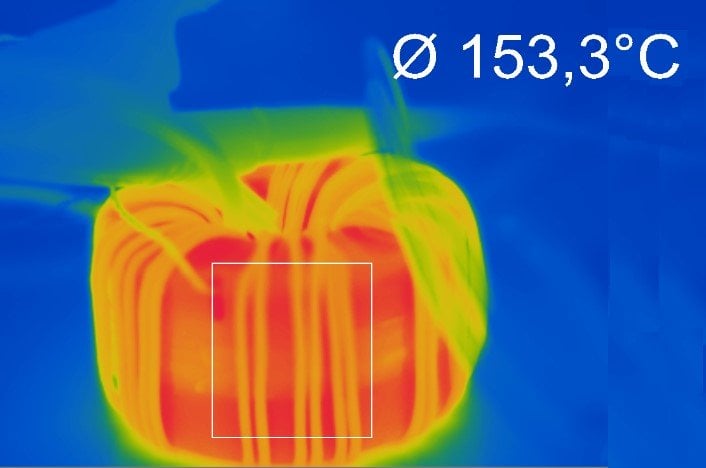
Figure 5: IR image of the LCP sample during the test.
Results showed that the final temperature was the same for all three samples. Nevertheless, the PA6 with higher thermal conductivity reached a steady temperature twice as fast as the other samples. This means that the “tau” coefficient of the PA6 4W/m·K sample in the lumped capacitance model equation is halved when compared to the rest.
A fast response system will show a faster ‘reaction’ to temperature variations, spreading the heat faster and therefore lowering the risks of ferrite cracks or hot spots. So, in this case, the use of high thermal conductive plastics had a significant impact on the thermal behavior of the part. In the next section, we will see if this also applies to the forced conduction approach.
Resins
In EV/HEV vehicles, all high-power magnetics must be cooled down by means of a forced cooling technique. Since semiconductor power modules are attached to a cooling plate, this is also used to mount the magnetic components on it. Most of our clients use only thermal pads, but there is a growing trend in the industry towards utilizing resins to pot the whole onboard charger or the power converter. The size of the power electronics units is reduced overall thanks to better thermal dissipation and electrical isolation of the resin.

Graph 1: Test results for different coil plastic.
We conducted a test with PA6 4W/m·K and LCP samples, both inside an aluminum case and potted with automotive silicone resin. The cases were mounted on a cooling plate with a thermal pad in between as shown in Figure 6. The purpose of this test was to check if thermal conductive plastics improve the design when potted with resins.

Figure 6: Test setup with the cooling plate.
Results confirmed that the final temperature of the samples was similar, with a difference of only 4ºC, which is negligible if we consider the accuracy of thermocouples and manufacturing divergences among samples. The time response of the system was slower for the PA6 sample (25% slower).
High Power Test Setup
To test the electrical and thermal performance of the 3DPower magnetics under all load conditions, a high-power test setup from MSPM Power GmbH was used. A TTG1000SIC square wave generator is the main part of the test equipment and it generates the square wave signal of up to 1000V. The square wave frequency can be set within a range of 10 kHz to 450 kHz and it is also possible to set the duty cycle from 0 to 100%. An external full-wave rectifier module (PCK-Module) is connected to the secondary side of the transformer, or the resonant circuit, to convert the AC signal into a DC voltage. With this test setup, it was easy to characterize the magnetic components under real-life conditions.
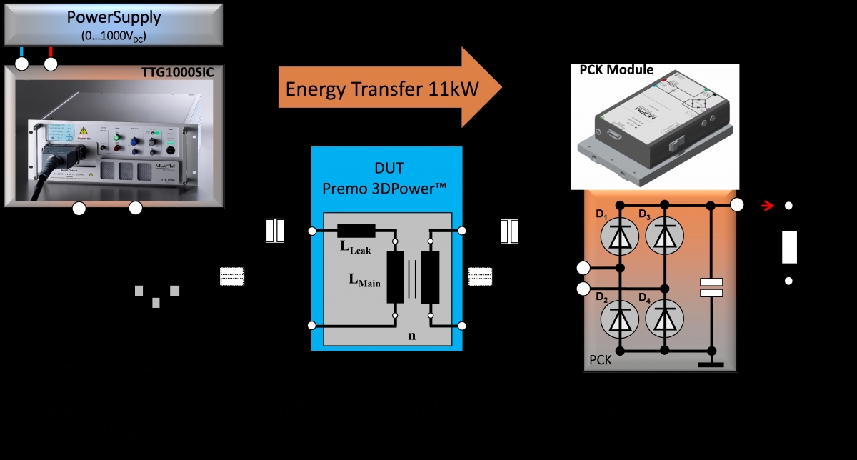
Figure 7: High-power test equipment.
Performance Test Results
Reliability of the components is a performance point often forgotten – we only care about it when there is an issue. Most of the reliability issues are related to temperature: fire, parameter variation, ferrite cracks, low performance, etc. For this reason, engineers must design and select the best materials to improve thermal behavior.
These results have shown the relevance of selecting the optimal materials in different scenarios. First, they emphasize the creation of good thermal links between all components of a transformer to achieve a continuous path for the heat to the cooling source.
Then, we tested how a simple thing like the adhesive of the cores could reduce the temperature gradient from 18ºC to 9ºC.
Finally, we confirmed that the combination of these results and good thermal conductor plastic can improve the heat dissipation in some cases; however, in other cases, it may not be worth it. When the part is potted with resin, a high thermal conductive plastic does not improve at all on a standard Liquid-Crystal Polymer plastic. The cost of the resin is higher, so the final decision is, as usual, a cost-performance tradeoff.
About the Author
Hector Perdomo Diaz is an R&D Engineer at Premo Group. He finished his Bachelor's Degree in Electronics at Universidad de La Laguna and had his Master's Degree of Industrial Engineering at Universidad de Las Palmas de Gran Canaria. As an Electronic Engineer, he had several years of significant and progressive experience as an automotive electronics engineer, expertise in power trains and DC/DC converters for electric and hybrid vehicles.