Facebook
 Google
 GitHub
 Linkedin
Reducing Noise in Automotive Fan-Based Cooling Systems
With the advancement of electrification in the automotive industry, active cooling is needed more often. When a fan is used, noise can become a problem. The following article explains the options for reducing noise and the considerations involved.
This article is published by EEPower as part of an exclusive digital content partnership with Bodo’s Power Systems.
With the advancement of electrification in the automotive industry, active cooling is more often needed. When a fan is used, airborne and structureborne noise can quickly become problematic. This article explains the options for reducing noise and the considerations to help you choose.
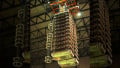
Power electronics applications with high power dissipation, small installation space, and low permissible noise levels are increasingly common, pushing active cooling designs (with fans and heat sinks) to the limits of physical feasibility.
Various factors must be considered to find the optimal solution, including the fan’s interaction with the system. However, any solution will be a compromise between size, speed, sound, and cost.

Image used courtesy of Bodo’s Power Systems [PDF]
Fans can be as quiet as a mouse when blowing in free air, but as soon as they are installed in a system, two issues may occur:
- Structureborne noise. The fan’s vibrations are carried on and amplified by the system, as in a violin case.
- Airborne noise. Due to the system’s airflow, additional turbulence may occur, creating a sound similar to how a flute works.
Considerations and Adjustments for Noise Reduction
First, pay attention to the fan’s operating point. Noise does not always increase in a straight line in step with the fan's speed. For example, 50% RPM does not equal 50% of the noise’s total volume. Furthermore, the volume at maximum speed is only relevant if the fan is supposed to spin at maximum speed.
The swirl or flow characteristics differ depending on the fan type and the rotor's blade geometry. Axial and centrifugal fans don't always blow in a straight line or blow out the same amount of air at each point of their air outlets. This affects the system because noise might occur if the airflow is disturbed.
Drawing air out of the system can reduce the noise level, but a fan needs to withstand a higher working temperature because it is drawing all the hot air in, increasing its temperature.
On the other hand, if a fan blows air into the system, it can be focused on a hotspot, if necessary, and disperse the heat or carry it away from the system’s main heat source. The fan's position in the device in relation to the user can also be a deciding factor as to which variant is better.
Using a larger fan and running it at a slower speed can quickly remedy the airborne noise due to a lower rotation speed, as a smaller fan would have to spin faster to achieve a similar result. However, the respective operating point must also be considered in this case. A smaller fan, compared to a larger fan, has a steeper characteristic line at the same operating point on a PQ-curve. Depending on the operating point, this can lead to the smaller fan operating in a more optimal area of its characteristic curve. Therefore, it is quieter than the larger fan.
However, “bigger” does not always refer to the same thing. It can mean scaling in all directions, the X and Y axes (width and height), or the Z axis (thickness). The latter case increases the pressure. X and Y scaling leads to both an increase in pressure and airflow.
\[\.V \sim n\cdot D^{3}\,\,\,\,\,\,\,\,\,\,\,\,\,\,\,\,\,\,\,\,\,\,Airflow\\
\Delta p\sim n^{2}\cdot D^{2}\cdot\rho\,\,\,\,\,\,\,\,\,\,\,Pressure\\
P\sim n^{3}\cdot D^{5}\cdot\rho\,\,\,\,\,\,\,\,\,\,\,\,\,\,\,\,\,\,\,\,\,Power\\
n=Speed\,of\,Rotation\\
D=Dimension\,(xyz)\\
\rho=Denity\]
Figure 1. Laws of proportionality to calculate the impact on pressure and airflow.
Adjusting the blade geometry can optimize the fan’s characteristic curve for the respective operating point and reduce noise development.
Changing the number of rotor blades to more or fewer blades can enable the fan to keep its performance values while spinning slower than before. It can also turn faster, but due to less resistance, the noise’s volume does not increase, or it may even decrease. This also allows an influence on the frequency spectrum.
The fan’s housing geometry can be optimized to reduce or change the flow of air turbulence between the fan and fins, finger guard, and air inlet and outlet. The system itself, which the fan is supposed to cool, can also be optimized, for example, by changing the airflow direction and the spacing of the fan in relation to other components, as well as by sealing holes, airborne noise can be reduced, while vibration dampeners can be used to decrease or avoid structure-borne noise.
Steps to Optimization
To optimize the fan and the system, you must consider:
- Power consumption
- Heat map (Where does the cool air need to go? What is the maximum allowed temperature for each component?)
- Available installation space, preferably via a 3D model or a sample
- Required lifetime
- Ambient temperature, as well as the maximum blow-out temperature => determines the necessary measures to achieve the required lifetime
If possible, information about past projects with similar requirements should be obtained. Two to three concept ideas will be evaluated for feasibility and cost.
As a result, a standard fan that comes closest to the requirements is selected and tested, if available. These test results are then used as a reference, and the standard fan may become the basis for a customized fan.
How To Avoid Noise Development
Simulations
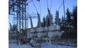
Simulations help reduce airborne noise and optimize the system's efficiency before prototyping begins. Having said this, the manufacturer should always carry out simulations because only the manufacturer knows its fan’s exact blade geometry. Without knowing that, it is only possible to roughly estimate the fan’s outflow. However, the fan’s outflow is often a deciding factor for determining what shape a heatsink should have, which orientation is most efficient, or whether the fan’s blade geometry should be adapted to an existing system.

Figure 2. Flow simulation. Image used courtesy of Bodo’s Power Systems [PDF]
A simulation could show:
- Where airborne noise will be generated due to the airflow
- If the system has been designed with the interaction of all thermal management components in mind
- Where material could be saved or replaced if the thermal management was better aligned and tuned to function as one system rather than individual components.
Single Component Testing
Single component testing is where noise optimization begins. It is important to note that a representative number of samples needs to be tested and measured for resonances over the entire range of their speeds because:
- Speed and noise do not necessarily increase with each other evenly. Due to certain conditions, noise spikes can occur at certain speeds, which means that, at times, a fan can reach higher noise levels at lower speeds than it does, for example, at maximum speed.
- Unbalance can be a problem not only at maximum speed but also at lower speeds. It can produce vibrations and noise and lead to a shortened lifetime.
- Motor cogging torque creates vibrations that can lead to audible resonances.
Based on the results of the vibration tests and the noise spectra, appropriate changes should be made to counteract the problems.
Each adjustment is tested at different operating points with the system at the relevant speeds and acoustically measured using 3D-printed or CNC-machined samples. It should be noted that this is not only about the overall sound pressure level but also about sound quality.
Example VW82469: No third band may protrude more than 3 dB on both sides simultaneously.

Figure 3. Diagram of Fan alone before system optimization (complies with standard). Image used courtesy of Bodo’s Power Systems [PDF]
Once the desired result has been achieved, it is necessary to condition the fans, depending on the customer’s requirements and industry standards, i.e., exposing the fans to various environmental conditions in a controlled environment, such as very high and low temperatures, often alternating, salt water as sprayed mist or immersed in a saltwater bath, and by running the fans constantly for a very long time under certain conditions.
After conditioning or at regular intervals during the process, the influence of the conditioning on the fans in terms of noise and other parameters is tested in more detail in so-called parameter tests. And if necessary, further improvements will be made.
Conducting such test series is often the norm in industries with very high reliability requirements, such as the automotive and energy sectors. The described tests and further tests are carried out in parallel or in sequence to qualify fans for use under difficult conditions.
System Testing
After successful simulations and tests on single components or in parallel with these, in-system tests are carried out based on various industry standards, like VW82469, which has been specifically developed for sound quality characterization, or the corresponding standards of other manufacturers. Physical tests are necessary for several reasons. To name just one: A spectral survey like VW82469 cannot yet be simulated reliably enough.

Figure 4. Diagram of Fan in the system (does not comply with standard). Image used courtesy of Bodo’s Power Systems [PDF]
These tests are part of the most important and final steps to virtually eliminate the risk of having to re-design the fan or the system shortly before the start of series production. In this context, particular attention should be paid to vibration tests to ensure there is no transmission or amplification of structure-borne noise because vibrations in the system can be much more pronounced than those of a single fan.
In existing systems where only the fan is replaced, system tests are often just another part of the parameter tests during each component's B-Sample and C-Sample phases, i.e., during the noise optimization outlined under “Single Component Testing.”
Suppose a system is developed in parallel with the fan, and thermal management and system are supposed to be properly aligned. In that case, fan manufacturers need samples of their customers’ systems, preferably after the design freeze, because any deviation from the final design could potentially contribute to less accurate results and prolong the optimization.

Figure 5. Diagram Fan after optimization in the system (complies with standard). Image used courtesy of Bodo’s Power Systems [PDF]
The conditioned and new fans are installed in the system, and parameter tests are carried out again during the B-Sample phase. The system and the fan are tested, usually in several runs, and the fan and the system are optimized. This could be fan or system component modifications, such as a heatsink being reworked to eliminate air resistance or openings responsible for noise or other system drawbacks. Once the optimization with the B-Samples is complete, design validation tests (DVT) begin, for which C-Samples like tooled parts based on the final design resulting from the B-Sample phase will be used. Normally, there should be no more surprises in the C-Sample Phase, and at most, fine-tuning should occur. In cases where an exception occurs and there are issues, another cycle of optimization and testing would follow. Otherwise, the C-Samples would be transferred to series production at the end of the DVT.
This article originally appeared in Bodo’s Power Systems [PDF] magazine and is co-authored by Karsten Witt and Tobias Schult of Finepower GmbH.