Facebook
 Google
 GitHub
 Linkedin
Half-Bridge vs. Sixpack Modules for Motor Drives
This article discusses how the implementation of three module approach can help lower the total cost of ownership and maximum junction temperature.
The use of one power module for each phase is state-of-the-art in solar and UPS applications even at relative small power ratings whereas in drive applications a single module for the whole application is commonly used.
PIM or Sixpack modules are most often used for low and medium power applications such as 3 phase motor drives since these modules have all the semiconductor switches in one housing. This simplifies the heat sink assembly because only one or two screws are required to mount these modules. A question that often arises is if lower semiconductor junction temperatures can be achieved by using a single Sixpack module or by using three individual half-bridge single-leg modules for a 3 phase inverter stage design.
In solar and UPS applications, it is state-of-the-art to use one half-bridge module for each phase whereas a single Sixpack power module is commonly used for motor drive applications. Several differences between these two applications are obvious:
On the one hand, variable frequency drives (VFDs) are designed in so call frame sizes. One frame size can have several power ratings. For the highest power rating of given frame size, the power module’s layout area is fully occupied with semiconductors and in the smallest power rating, the same module footprint and pinning is used with much smaller semiconductor die sizes. If a higher power rating is required, the next power module size is considered which usually results in a large frame size. In contrast to solar and UPS applications, no consideration for frame sizes exists since these inverters are not assembled in control cabinets where the width and the height is limited.

Figure 1: 3 x flow 0 housings vs. 1 x flow 2 housing
Solar and UPS applications provide a fixed grid frequency of 50 Hz or 60 Hz which leads to a lower ripple and variations in the semiconductor’s junction temperature. In contrast, many motor drive applications have to provide full power even at a rotor speed of 0 RPM which leads to high stresses on the bond wires due to high currents. This requires the VFD to be designed to support an overload current capability as high as 300 % in some applications. This means that the inverter has to be designed and be able to provide 3 times the nominal inverter current for a specified time period which can last for many cycles.
UPS applications do not have to deal with these high currents too often. The high current requirements for UPS applications are lower and are only necessary to open circuit breakers and fuses during failures and fault conditions. Solar applications do not have these high overload current requirements at all.
Three Module Versus Single Module Approach
The most important parameter to consider in this comparison is the junction temperature of the semiconductors under a given condition and environment. Figure 2 shows two simulation results with a given aluminum heat sink at an ambient temperature of 40°C and an airflow of 3m/s blowing from the bottom through the heat sink fins. The heat sink base has a thickness of around 8mm and the fins have a length of 50mm. The left picture shows the temperature rise of three half-bridge modules using an Al2O3 DCB each with 60W losses and the right picture shows a Sixpack module based on a 3mm copper baseplate with 180W losses. For this comparison, the same current rating and semiconductor technology and material is considered. The spacing between these three modules is selected to be 13mm, and the modules are positioned on the left side of the assembly to allow space for the input filter, control board, etc. located on the right side of the assembly.
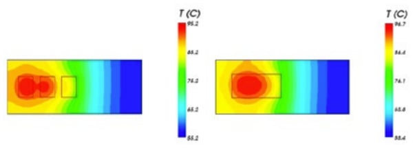
Figure 2: 3x flow 0 Al2O3 with each 60 W losses vs. 1x flow 2 with 180 W losses
Comparing these two thermal images, it can be seen there is little difference in the heat sink base temperature profile. Using the given Rth values from the modules’ datasheet, the semiconductor junction temperature can be calculated and are shown in Table 1: No real advantage can be seen from this comparison. In contrast, there seems to be a disadvantage if three individual half-bridge modules are used instead of a single Sixpack module. The reason for these poor results is because the three individual half-bridge modules were placed too close to each other and the worse Rth due to the missing baseplate resulted in higher junction temperatures. The RMS current chosen in these examples was only 1/3 of the nominal 75A chip current rating and was driven with a switching frequency of approximately 5kHz.
| 3x flow 0 Al2O3 | 1x flow 2 | |
| Module losses / W | 60 | 180 |
| Heat sink temperature / °C | 95 | 97 |
| IGBT Junction temperature / °C | 112 | 108 |
| Diode Junction temperature / °C | 102 | 92 |
Table 1: Losses and temperatures of 3x flow 0 Al2O3 and 1x flow 2
The next simulation shown in Figure 3 shows the temperature distribution on the heat sink when the three half-bridge modules were spaced further apart and placed in an optimized arrangement.

Figure 3: 3x flow 0 Al2O3 with each 60 W losses optimally distributed
The temperatures are shown in Table 2:
| 3x flow 0 Al2O3 | |
| Module losses / W | 60 |
| Heat sink temperature / °C | 82 |
| IGBT Junction temperature / °C | 99 |
| Diode Junction temperature / °C | 89 |
Table 2: Losses and temperatures of 3x flow 0 Al2O3 optimal located
In this case, the semiconductor junction temperatures of the optimally distributed modules were 13 K lower compared to a single power module located on the left side. This is exactly the difference of the heat sink temperature compared to the simulation where the three individual modules were closely spaced. However, the complete mechanical assembly concept needs to be considered when placing other components around these modules to optimize these lower temperatures.
Handling three smaller power modules can be more difficult than handling a single larger module. Another challenge might be the module’s housing tolerance. Different module heights after soldering results in stresses on the PCB and the components mounted on these PCBs. Pull forces on the pins of the power module have to be avoided to minimize mechanical stresses. To eliminate the challenge of different module height tolerances, all power modules at Vincotech are also available with Press-fit pins. With this highly reliable interconnection technology, all modules can be pressed into the PCB and maintain the same height to the heat sink assembly eliminating possible mechanical stresses.
One crucial factor to take into consideration for this comparison is the total cost of ownership. It is difficult to estimate the costs for changing the location of other components such as capacitors and inductors placed around the module. It is also difficult to estimate the costs of assembly due to different manufacturing processes and locations. However, as a module manufacturer, the costs of the different sized power modules are known and price comparison of the different options can be made.
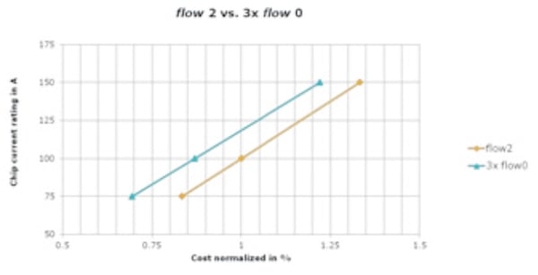
Figure 4: flow 2 vs. 3x flow 0
As can be seen in Figure 4, the flow 2 Sixpack module is slightly more expensive when compared to three flow 0 half-bridge modules with the same chip current rating. This is because of the additional copper baseplate of the flow 2 module that holds 3 DCBs with one half-bridge on each DCB. From a cost perspective, the difference between these two options is 10% to 15% dependent on the current rating.
The implementation of three flow 0 half-bridge modules instead of one Sixpack flow 2 module for motor drive applications was considered in this discussion. The resulting junction temperatures depend highly on how well multiple power modules can be placed on a given heat sink to distribute the heat generated in these modules. Three flow 0 half-bridge modules placed close to each other will result in the even higher junction temperature of the semiconductors compared to one flow 2 Sixpack module. Optimized distribution of flow 0 half-bridge modules results in much lower junction temperature. Also, from a cost point of view, the flow 0 half-bridge module without a massive copper baseplate is less expensive in this approach. If multiple modules are handled correctly, their maximum semiconductor junction temperature and their total cost of ownership can both be lowered.
About the Author
Patrick Baginski is a field applications engineer at Vincotech GmbH. He regularly writes articles pertaining to power modules, discussing such topics as IGBTs, power module mounting, and power conversion. He earned his Bachelor's Degree in Engineering at the University of Applied Sciences South Westphalia Abt. Soest, Germany.
This article originally appeared in the Bodo’s Power Systems magazine.