Facebook
 Google
 GitHub
 Linkedin
Generation 7 IGBTs: The New Workhorse in the Power Electronics Industry
This article highlights SEMIKRON IGBT Generation 7 that features four main advantages compared to previous generations.
The 1200V Generation 7 IGBTs are the new workhorse in the power electronics world. They are specifically designed for motor drive applications and at SEMIKRON available from two different suppliers. This ensures supply chain safety paired with the highest performance in four different packages.
IGBT Generation 7 features four main advantages compared to previous generations. Besides a) higher reliability thanks to increased humidity robustness these are b) lower conduction losses (Vce, sat), c) an increased overload capability, and d) a smaller physical chip size.
Thanks to the smaller size of Generation 7 IGBT chips with the same nominal chip current, it is now possible to accommodate a larger nominal chip current in the same module package. This results in two possible options to use Generation 7 IGBTs: Either in the same current rating but smaller chip area or with the same chip area and increased nominal current rating.
The conduction losses of the IGBT Generation 7 are lower while the switching losses are similar to those of Generation 4. Therefore, the total losses are also lower. In contrast, the Generation 7 IGBT chip now has a higher thermal resistance Rth(j-c) due to its smaller size, and thus poorer cooling. Nevertheless, smaller losses result in higher efficiency and lead to lower cooling effort for the semiconductor modules.
This work dives deep into the practical examples implementing Generation 7 IGBTs and highlights the resulting benefits. It is based on two of the four SEMIKRON power modules equipped with Generation 7 IGBTs. These are SEMiX 3 Press-fit and MiniSKiiP, both the dominating packages in motor drive applications. In both packages, the nominal current range can be extended by replacing IGBT 4 with IGBT Generation 7.
The maximum nominal current with IGBT 4 in SEMiX 3 Press-fit is 600A with the SEMiX603GB12E4 half-bridge. With the IGBT Generation 7, the maximum nominal current increases by 16% to 700A in SEMiX703GB12M7, while the 600A version SEMiX603GB12M7 is also available.
Within the MiniSKiiP series, we will look into the biggest six-pack power modules. Based on IGBT 4, the SKiiP39AC12T4V1 is fitted with a 3-phase inverter output with a nominal IGBT current of 150A. Switch-ing to Generation 7 IGBTs, two options become available in the same package. The first option is fitting the same nominal chip current to make a SKiiP39AC12T7V1 with a 150A nominal current. Alternatively, the same IGBT chip area with a higher nominal current can be embedded into SKiiP39AC12T7V10. This makes it a 200A rated power module. Of course, the MiniSKiiP with IGBT Generation 7 is also available in other popular motor drive topologies like CIB (Converter-Inverter-Brake) and half-bridge configurations.
Motor Drive Applications
In motor drive applications the IGBT is usually the power-limiting semiconductor device. Electrical machines have a power factor cosphi of 0.7 to 0.95. Therefore, during each switching cycle in motor drive applications, the current flows through the IGBTs longer than the antiparallel freewheeling diodes. This is where Generation 7 IGBTs can make the most out of their advantages.
Before looking into a detailed comparison, let’s have a closer look at a further advantage of the Generation 7 IGBT: the improved EMC behavior in motor drive applications. The voltage slew rate (dv/dt) at the inverter output of modern IGBT chips is usually relatively high due to their fast switching behavior. Together with the cable capacitance, this voltage change causes a parasitic capacitive leakage current Icap. It flows through the cable capacitance of the motor cable shields and the winding capacitance of the motor towards earth potential. It is calculated as Icap = (Ccable + Cmotor) * dv/dt and occurs as current peaks with every switching instance.
This results in conducted and radiated interference emissions from the drive. These emissions must be reduced to certain limit values due to the norms and standards to be observed. HF EMC filters are used for this purpose. Additionally, a high capacitive current is added to the motor drive output current and a drive with higher nominal current might have to be selected. Moreover, the capacitive currents lead to additional power losses in the semiconductor module. Finally, a high dv/dt value might also generate motor bearing currents, resulting in premature bearing failures and the use of expensive insulated bearings.
Reducing the dv/dt value will reduce the capacitive currents and with this all above-mentioned risks. On the other hand, slower switching will result in an increase of switching losses, reducing the efficiency of the motor drive. A relatively slow switching IGBT with low switching losses is therefore advantageous. Here IGBT Generation 7 will greatly help to achieve low dv/dt values and acceptable switching losses at the same time.
Turn-ON behavior When the IGBT is turned ON, the current commutates to this IGBT from the complementary freewheeling diode and vice versa when it is turned OFF. Therefore, the switching speed of the IGBT does not only influence the electromagnetic emission, it also affects the IGBT and diode switching losses.
As a general rule of thumb, faster IGBT turn-ON reduces the IGBT losses and at the same time increases the diode losses. Since the diode losses are much lower than those of the IGBT, the resulting total losses are dominated by the IGBT. Nevertheless, the diode losses cannot be fully ignored. The gate resistance sets the switch-ing speed of the IGBT. The junction temperature and the load current have a considerable influence on that speed. In order to find an EMC-optimized IGBT switching speed, it is useful to first define the gate resistance with which the highest switching speed can be obtained. For both IGBT 4 and IGBT Generation 7, this is the case at a) cold (room) junction temperature and b) relatively low current values.
The temperature influence of Generation 7 IGBTs is much smaller than that of its predecessor. For example, we compare the voltage slopes of the two 600A rated SEMiX 3 Press-fit modules with IGBT 4 and IGBT Generation 7. The comparison refers to a system with 600V DC-link voltage and a load current of 300A. At a junction temperature of 150°C and with a turn-ON gate resistor of 2Ω, both generations show a dv/dt value of 2.5kV/μs. At 25°C, the voltage slope of the Generation 7 IGBT rises to a moderate 4.2kV/μs, whereas the IGBT 4 exceeds 15kV/μs.
A dv/dt of 4.2kV/μs is an acceptable value for general purpose motor drive applications. As the highest voltage slope occurs at low temperatures, the lowest possible gate resistor must be determined at room temperature. In order to limit the voltage slope to 4.2kV/μs, the IGBT 4 turn-ON gate resistor must increase from 2Ω to 4.8Ω. The switching losses increase with the junction temperature, so the power loss comparison should be done at an elevated temperature of 150°C. Here, the increased gate resistors result in an increase of IGBT turn-ON losses for IGBT 4 from 30mJ to 48mJ (+60%). As explained above, the diode losses reduce as the IGBT turn-ON losses rise, in this case from 20mJ to 17mJ (-20%).
Due to the dominance of the IGBT losses, the combined turn-ON losses at turn-ON of one IGBT 4 switch increase by 28% to 64mJ at 4.2kV/μs compared to 15kV/μs voltage slope. This is slightly more than the Generation 7 IGBT at 62mJ. Figure 1 shows the exact de-pendency of dv/dt at 25°C and switching losses at 150°C versus the turn-ON gate resistor.
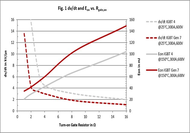
Figure 1: dv/dt and Eon vs. Rgate,on
Turn-OFF Behavior
During turn-OFF, the voltage slope dv/dt increases with the current. Therefore, during turn-OFF most of the interference emissions occur with large load currents. With cooler junction temperatures, the volt-age slope increases as it does during the turn-ON of the IGBT, but the effect is much less pronounced. In general, the voltage gradients are also smaller when the IGBT is turned OFF than when it is turned ON. However, the influence of the gate resistance on the voltage slope is also only very limited. In summary, the operating point with the high-est electromagnetic noise emission is at cold temperature and high current. This applies to both IGBT generations 4 and 7.
Comparing again the 600A rated SEMiX 3 Press-fit power modules, the voltage slope at IGBT turn-OFF of the IGBT Generation 7 is about 20% higher than that of IGBT 4. In order to achieve the same noise emission for both IGBT generations, a higher-impedance gate resistor must be used for SEMiX603GB12M7. This will increase the turn-OFF losses. The target is again to limit the voltage slope to 4.2kV/μs, the same as at turn-ON. A turn-OFF gate resistor of 7.1 Ohm is required for the IGBT 4 compared to 12 Ohm for Generation 7. This results in similar turn-OFF losses of 41mJ for the SEMiX603GB12E4 and 42mJ for the SEMiX603GB12M7 as Figure 2 shows.
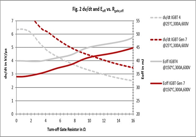
Figure 2: dv/dt and Eoff vs. Rgate,on
Lower Losses, Higher Power
The total switching losses are the sum of the turn-ON and turn-OFF losses of the IGBT and the switching losses of the freewheeling diode. If the voltage slope is limited to 4.2kV/μs the total switching losses of both IGBT generations with the same nominal module current of 600A are roughly the same with 104mJ for the IGBT Generation 7 and 105mJ for IGBT 4. Nevertheless, thanks to the 20% lower saturation voltage Vce,sat the overall power losses of the Generation 7 IGBTs are lower. For a direct comparison, we look at the power losses with the previously selected gate resistors, a PWM frequency of 2kHz and a maximum junction temperature of 150°C.
In comparison, Generation 7 IGBTs can reduce the losses by 13% from 504W per switch to 439W per switch (SEMiX603GB12M7p) or by 19% to 409W per switch (SEMiX703GB12M7p) (Figure 3).
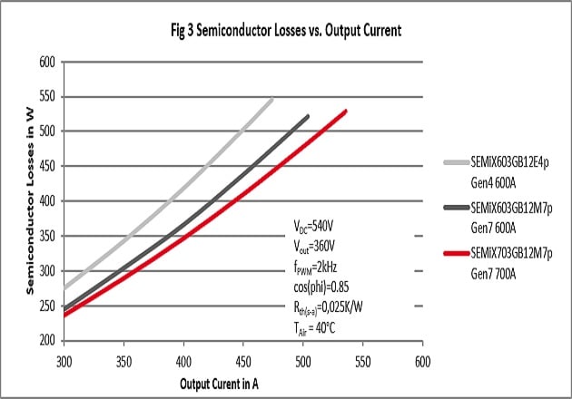
Figure 3: Semiconductor Losses vs. Output Current
These lower losses convert directly into savings on the electric power bill. In this example, the loss savings are 95W per switch. Considering electricity cost of 0.10€/kWh and 4000h operation hours per year, this results in immediate cost savings of 228€ every year (6*95W*4000h/a*10ct/kWh=228€/a). Besides this secondary benefit, cooling efforts can also be reduced. Losses that do not occur at all do not heat up the semiconductors and do not need to be dissipated. Further savings can be achieved in the heat sink design or the cool-ing of the cabinet where the motor drive is installed. In another use case, the economic viability results from frame-size jumps and a higher power density on the system level: the same housing size can now be rated for a higher nominal inverter current, considering the recommended junction temperature of 150°C as the design limit. It can be increased from 473A SEMiX603GB12E4 to 506A (+7%) with the SEMiX603GB12M7. Choosing the SEMiX703GB12M7 it even increases to 536A (+13%). Figure 4 shows the detailed comparison for 2kHz PWM frequency.
Moving to the MiniSKiiP we do a direct comparison of the above mentioned three six-pack modules based on application data shows the benefits of IGBT Generation 7: For the same load current (here
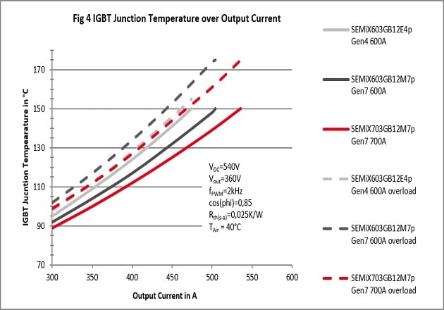
Figure 4: IGBT Junction Temperature over Output Current
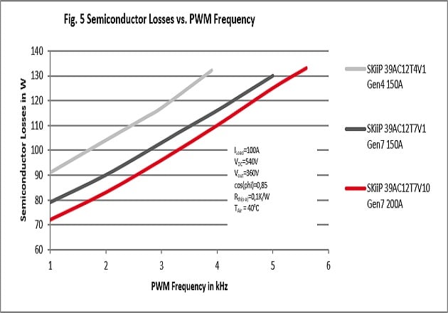
Figure 5: Semiconductor Losses vs. PWM Frequency
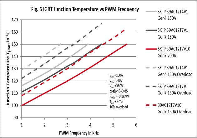
Figure 6: IGBT Junction Temperature vs PWM Frequency
The power dissipation of Generation 7 IGBTs in MiniSKiiP is significantly lower than that of IGBT 4, e.g. 15% (12W) at 2kHz for the same chip current, increasing to even 24% (19W) for the larger chip. This results in savings of electricity cost of over 45€ per year for the user, based on electricity cost of 0,10€ per Kilowatt-hour and 4000h operation per year (6*19W*4000h/a*10ct/kWh=45.60€/a) compared to IGBT 4. As an alternative to the higher efficiency, the lower power dissipation enables increasing the load current or the PWM switching frequency. Thus, for a load current of 100Arms with IGBT 4, only 3.9kHz switching frequency is possible. With Generation 7 IGBTs using the same nominal chip current, 4.5kHz is possible and with the bigger chip current even 5.6kHz (Figure 6). The limiting factor is the maximum recommended junction temperature for continuous operation of 150°C permissible for the IGBT chip. The second alternative could be to increase the continuous load current from 115A to 122A (Generation 7 with 150A) or even 138A (Generation 7 with 200A) at 2kHz PWM frequency.
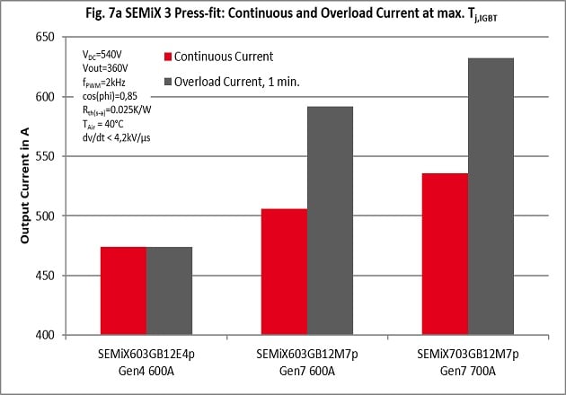
Figure 7a: SEMiX 3 Press-fit: Continuous and Overload Current at max. Tj,IGBT
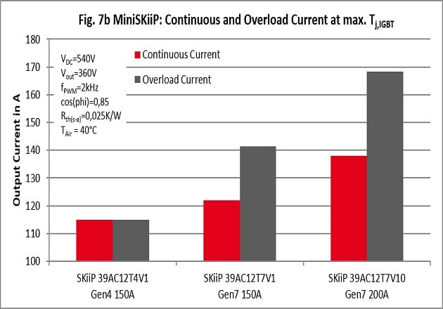
Figure 7b: MiniSKiiP: Continuous and Overload Current at max. Tj,IGBT
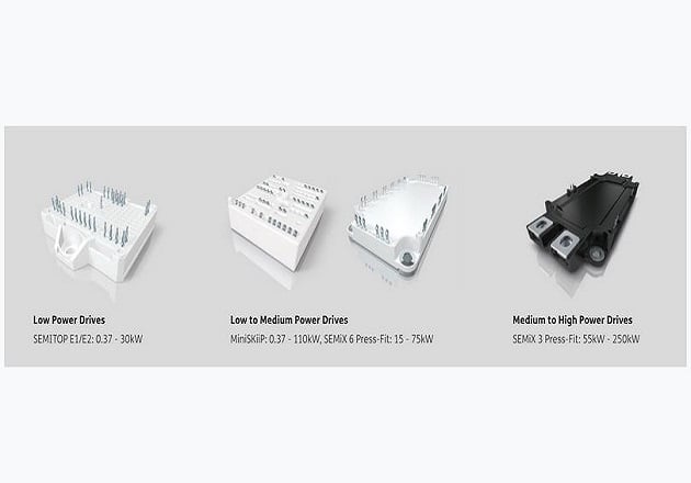
Figure 8: Initial SEMIKRON product line-up using IGBT Generation 7
Overload Currents
Using IGBT 4, no additional overcurrent is possible as it is not recommended to exceed the junction temperature of 150°C for safety reasons. However, IGBT Generation 7’s additional temporarily allowed junction temperature enables a chip temperature to increase up to 175°C for one minute. Replacing the SEMiX603GB12E4 with Generation 7 IGBTs results in overload currents of 592A for SEMiX603GB12M7 and 632A for SEMiX703GB12M7 (Figure 7a).
For the MiniSKiiP, an additional overload current of up to 1.12 times or 1.14 times the continuous load current can be utilized for up to one minute (Figure 7b). If an overload current was necessary using IGBT4, the continuous current must be reduced by 9%, from 115A to 105A, to allow a 10% short-term overcurrent for 1 minute.
The Overall Benefit of 7 IGBTs
Generation 7 IGBTs bring several benefits to motor drive applications when compared to previous IGBT versions. Besides the increased reliability of the new chip technology, the smaller size, lower forward losses, and the optimized switching performance allow for higher power density in given power module packages.
In motor drive designs specifically, the dv/dt on the inverter output side is one of the major design restrictions. IGBTs of the 7th Generation exhibit lower power losses at a fixed dv/dt compared to IGBT4. Consequently, this efficiency increase leads to immediate savings in the Total Cost of Ownership (TCO). Alternatively, in a given design, the lower power losses can be converted into higher output power or higher PWM frequencies. Additionally, it is possible to consider the built-in overload function in the inverter specification without the need for an explicitly designed reserve, as is the case with IGBT 4.
Generation 7 IGBTs are currently available in SEMITOP E1/E2 (0.37 to 30kW), MiniSKiiP (0.37 to 110kW), SEMiX 6 Press-fit (15 to 75kW) and SEMiX 3 Press-fit (55 to 250kW and higher), see Fig. 8. The baseplate-less MiniSKiiP and SEMITOP packages include CIB and sixpack topologies, the MiniSKiiP also covers half-bridge topologies. The SEMiX 6 Press-fit is a baseplate design available as CIB and sixpack. The SEMiX 3 Press-fit is a half-bridge module, which has a base plate as well. Rectifier modules in the MiniSKiiP and SEMiX packages complete the portfolio, to offer a full motor drive solution, made by SEMIKRON.
About the Authors
Stefan Häuser has a diploma in Electrical Engineering. From 2001 to 2011 he worked as a group leader in engineering for industrial motor drives. Joining SEMIKRON in 2011 as a product manager, he changed to his current position as senior manager of product marketing for the complete range of power modules in 2015. Besides the IGBT and thyristor/diode-based power module market, he also focuses on silicon carbide power module strategy.
Rainer Weiss worked as an application manager at SEMIKRON.
This article originally appeared in the Bodo’s Power Systems magazine.