Facebook
 Google
 GitHub
 Linkedin
EconoDUAL 3 has Highest Power Density and Performance Using New IGBT7
This article highlights Infineon chipset of IGBT7 and emitter-controlled 7 diode that is user-friendly and optimized to fulfill the GPD requirements.
The development of the new semiconductor generation targets a current density increase with the aim to reduce system costs for inverter manufacturers. It is crucial that the new technology is implemented in a given module footprint to facilitate the upgrade of existing inverter systems. This approach leads to fast market penetration.
For this to happen, the switching characteristics of the improved IGBTs and diodes have to fit the characteristics of the selected module housing. This is true, especially with regard to oscillation behavior, since the module current is higher, and the reduction of module stray inductance is limited. At the same time, improving the housing is an important consideration to be able to handle higher currents and temperatures.
The benefits of the new device are clear: higher inverter output current for the same frame size and avoidance of paralleling of IGBT modules. Both of these advantages help to simplify inverter systems and to lower costs. In this paper, the technical aspects of the new EconoDUAL™ 3 with TRENCHSTOP™ IGBT7 for general-purpose drives application will be discussed.
Target Application
One target application for the new IGBT7 generation is the general-purpose drive (GPD) application in a power range above 90kW. It is important to consider the typical application parameters to understand the improvement levers to achieve a benefit compared to the predecessor IGBT4 technology.
Typically, switching frequencies for GPDs in the power range above 90kW are in the range of 2kHz to 2.5kHz [1,2]. Most inverter manufacturers use advanced modulation methods, such as discontinuous pulse width modulation (DPWM) [3], that lead to a reduction of switching losses by half, compared to traditional continuous modulation [4].
For the IGBT7 Development
For the IGBT7 development and for the following study, switching frequencies of 1kHz and 2.5kHz, both as continuous PWM, are selected to evaluate the new technology. The results are valid for higher switching frequencies using DPWM. A characteristic of this application is the use of an air-cooled heatsink of extruded aluminum at a maximum ambient temperature of 40°C.
Nominal Current of the GPD Inverter
The nominal current of the GPD inverter is dimensioned taking into account normal and heavy-duty overload pulses at different overload current levels. Therefore, the maximum allowed IGBT operation temperature must also consider this type of operation.
Maximum Steepness of the Voltage Slope
Finally, the maximum steepness of the voltage slope (du/dt10-90%) during IGBT turn-ON and turn-OFF is typically limited to maximum 5kV/μs due to the motor winding lifetime and drive-shaft corrosion [5] as well as to electromagnetic compatibility (EMC). A simulation using the application parameters mentioned above is implemented with the power electronic module FF60012ME4_B72. The results are shown in Figure 1.
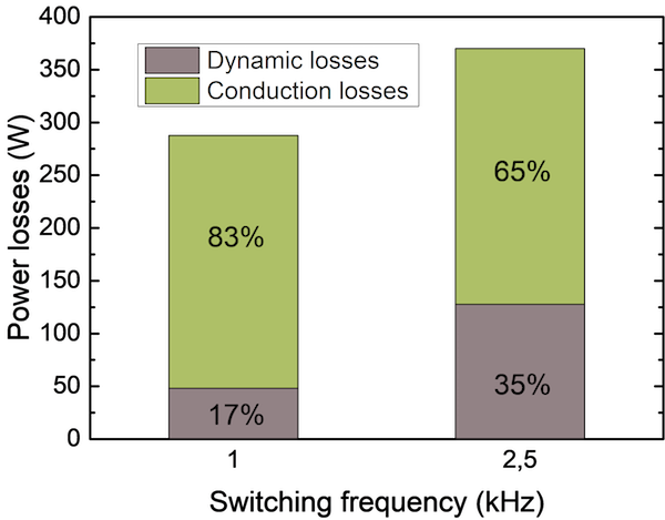
Figure 1: Loss distribution FF600R12ME4_B72 at 350 A and typical GPD conditions for this power class
It becomes visible that the conduction losses of the IGBT and diode predominate the dynamic losses. At 1kHz these losses represent 83% and at 2.5kHz 65% of all semiconductor losses. This, with the fact that the switching speed for electrical-motor-related applications cannot be increased above 5kV/μs, concludes that the main lever for device optimization is the static loss reduction.
Static Losses
The corresponding normalized output characteristics of the IGBT7 micro-pattern trench MPT technology and the IGBT4 are presented in Figure 2 for temperatures of 25°C, 125°C, and 150°C, and for the TRENCHSTOP IGBT7 additionally 175°C. A reduction of VCE, sat from 2.05V to 1.70V by 350mV at nominal current is observed when comparing both IGBT technologies, which demonstrates the optimization of the device.

Figure 2: Normalized output characteristics of the 1200 V TRENCH-STOP™ IGBT4 medium power compared with the 1200 V TRENCH-STOP IGBT7, measured at Vge=15 V
Dynamic Switching
The turn-ON losses (Eon) of the 900A IGBT7 module are lower than those of the 600A IGBT4 module when a similar collector current is turned ON. In fact, the reduction of the saturation voltage and the given device softness result in higher turn-OFF losses for the 900A IGBT7 compared with the 600A IGBT4 at similar collector currents. The values are presented for both chip technologies in Figure 3.
Figure 3: Turn-ON losses Eon of the FF600R12ME4_B72 and the FF900R12ME7_B11 as a function of the collector current Ic. The insert shows Etot, the sum of Eon and Eoff
The chosen external gate resistances coincide with the datasheet values, which have been defined in such a way that switching without cut-off oscillations of the IGBT and diode at 25°C is ensured.
Moreover, quite similar du/dt values are present for the FF600R12ME4_B72 and the FF900R12ME7_B11 at those gate resistances for turn-ON and turn-OFF. As a result, the total IGBT losses (Etot) which are the sum of Eon and Eoff remain nearly the same (see insert in Figure 3). Below 600A, both modules show identical losses.
IGBT and FWD Junction Temperature Specification
While the IGBT4 has a specified absolute maximum temperature of Tvj(op) equal to 150°C, without differentiation between continuous and overload operation, the IGBT7 Tvj(op) specification is made taking into account the typical overload scenarios specified by the drives manufacturers, and can cover the three seconds as well as the 60 seconds overload pulses. For continuous operation, the IGBT7 is specified for 150°C and for overload operation 175°C for a maximum of 60 seconds [6].
Application Tests and Results
All the characteristics of the newly developed FF900R12ME7_B11 described above will lead to improved performance, compared to the FF600R12ME4_B72 device. To evaluate and compare the performance of these two devices, a series of application tests were performed. The temperatures were evaluated with an infrared camera. The test parameters were set with the information described in Chapter 1 and listed in Table 1.
Table 1: Test Parameters to Compare IGBT7 and IGBT4*
| Topology | H-Bridge |
| Heatsink | Air-cooled heatsink |
| Switching frequency | 1 and 2.5 kHz |
| Modulation method | Continuous PWM |
| Gate-Emitter voltage | -8 V to +15 V |
| DC-Link voltage | 621 V |
| Modulation index | 0.95 |
| cos phi | 0.9 |
| du/dt10-90% | < 5 kV/μs |
| IR-camera picture rate | 30 pictures per second |
| Ambient temperature | 20°C* (40°C) |
*Typical GPD parameters used to compare IGBT7 with IGBT4 in the application. The required ambient temperature of 40°C cannot be adjusted with the test setup.
Output Current and Temperature Reduction
The results of the experiment are exemplary for a switching frequency of 1kHz visualized in Figure 4.
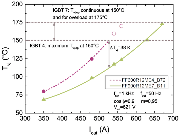
Figure 4: IGBT junction temperature as a function of output current at 1kHz and conditions described in Table 1
It becomes visible that at 1kHz continuous PWM and the same output current, the module using the IGBT7 technology operates at 38K lower temperature compared to the IGBT4 device. Pushing the new module to the limit of the specified temperature leads to 150A higher output current. At 150°C, the IGBT7 still has the advantage of 95A more, compared to the IGBT4.
Also at 2.5kHz continuous PWM modulation, the benefit of the new technology is significant with 33K lower temperature at the same current, 70A at 150°C, and 110A at 175°C more maximum output current are possible.
DC-terminal Temperature Reduction
Figure 5 illustrates the temperature reduction achieved using the new housing of the FF900R12ME7_B11 compared to the FF600R12ME4_B72.
Figure 5: Temperature improvement comparing the DC-busbar temperature of the new and former housing
The new housing of the FF900R12ME7_B11 module leads to a temperature reduction of up to 20K on the DC busbar compared to the FF600R12ME4_B72 at the same output current.
GPD Frame Size
In this part of the test, the parameters regarding output current for normal duty (ND) and heavy-duty (HD) of a GPD manufacturer [1] were selected to evaluate the maximum possible frame size current for the different technologies. The parameters are listed in Table 2.
Table 2: Selected Test Parameters for Frame Size Capability
| Frame size 370A (A) | Frame size 477A (A) | |
| Rated current IND | 370 | 477 |
| Normal-duty60 s 1.1 x IND | 407 | 525 |
| Normal-duty3 s 1.5 x IND | 555 | 716 |
| Rated current (IHD) | 312 | 370 |
| Heavy-duty60 s 1.5 x IHD | 468 | 555 |
| Heavy-duty3 s 2 x IHD | 624 | 740 |
The rated output current was applied on the semiconductor at the conditions described in Table 1, at 2.5kHz. The temperature of the entire system was in a steady state before overloading the current application. The thermal behavior of the system is shown in Figure 6. The IGBT4 solution is at the temperature limit with frame size 370A. During the three-second-heavy-duty overload pulse, the IGBT Tvj achieves a value of 142°C.
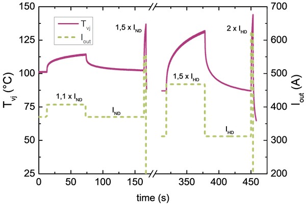
Figure 6: Frame size 477A, FF900R12ME7_B11 device: measurement results at rated current ND and HD, normal duty and heavy-duty overload pulses
Requirements of the 477A Frame Size
The IGBT7 device is able to fulfill the requirements of the 477A frame size. At all required current levels, the FF900R12ME7_B11 is still within the IGBT7 specification presented [6].
Since the ambient temperature in the test was 20°C instead of the required 40°C, the achieved results are valid for the purpose of comparison. Inverter manufacturers can achieve the same output current at 40°C by using an improved heatsink, using discontinuous PWM, and/or reducing the switching frequency.
IGBT7 for General-purpose Drive Requirements
The newly developed chipset of IGBT7 and emitter-controlled diode EC7 is user-friendly and optimized to fulfill the general-purpose drives (GPD) requirements. A significant reduction of static losses, good controllability, sufficient softness at all application-relevant current levels, and high short-circuit capability is achieved. The improvement in the EconoDUAL 3 housing and the new temperature specifications for covering the drives overload requirement result in a high degree of freedom for the inverter design engineer.
The conducted application tests have impressively demonstrated improved performance compared to the former generation. The new FF900R12ME7_B11 achieves 38K lower temperature compared to the FF600R12ME4_B72 module at the same current.
Alternatively, up to 150A higher output current can be achieved. Bearing in mind the typical GPD normal-duty and heavy-duty design criteria, a frame size jump from 370A to 477A is possible with the EconoDUAL 3 housing using IGBT7 instead of IGBT4.
About the Authors
Klaus Vogel is a Technical Marketing Manager, as well as an Application and System Engineer at Infineon Technologies. He is a Certified Electrotechnical Assistant at Eduard-Spranger-Berufskolleg Hamm. Vogel has a diploma in Electrical Engineering, Electrical Power Engineering, and Environmental Engineering at the University of Applied Sciences and Arts Dortmund. After he graduated, he began as Complaint Management and Failure Analysis personnel in 2008 at Infineon.
Christoph Urban is working at Infineon, in which Infineon Technologies AG is a world leader in semiconductor solutions such as smart functions, security solutions, and technologies reduce energy consumption in cars, trains, industrial plants, consumer electronics, and household appliances.
References
[2] SINAMICS G120, Power Module PM240, Hardware Installation Manual 072009, Page 65
[3] M. Depenbrock: Pulse width control of a 3-phase inverter with nonsinusoidal phase voltages in Conf. Rec. IEEE Int. Semiconductor Power Conversion Conf., 1977, pp. 399–403.
[4] M. Bierhoff, et al., An Analysis on Switching Loss Optimized PWM Strategies for Three-Phase PWM Voltage Source Converters, The 33rd Annual Conference of the IEEE Industrial Electronics Society (IECON), Nov. 5-8, 20
[5] K. Vogel, et al., Improve the efficiency in AC-Drives: New Semiconductor solutions and their challenges, EEMODS 2016, Helsinki
[6] AN2018-14, TRENCHSTOPTM 1200 V IGBT7 Application Note