Facebook
 Google
 GitHub
 Linkedin
The Development and Performance of an Integrated Gate Commutated Thyristor (IGCT)
This article discusses the Integrated Gate Commutated Thyristor and its different segment layouts.
The IGCT is a semiconductor switch with low on-state loss, making it ideal for medium to the highest power inverters; an application that must strive to maximize power output and energy efficiency to deliver a competitive product. Although application-specific aspects including topology, switching frequency, and output filters are principal contributors to inverter efficiency, the semiconductors themselves can make a significant contribution by offering low on-state and switching losses. In this respect, the IGCT is undoubtedly the highest-performance silicon device architecture.
The development and performance of a 6500 A, 4500 V Integrated Gate Commutated Thyristor (IGCT) is described in this article. Different segment layouts were investigated with the goal of maximizing the controllable current, and these tested layouts are described below. The mechanical design is based on an existing platform for outer-ringgate, 94 mm-diameter silicon wafers. The best layout variant reliably switches currents exceeding 8000 A at 2800 V in a single pulse, with stable frequency operation up to a virtual junction temperature of approximately 230 °C.
Device Architecture
The project aimed to use the lower thermal impedance and increased active area of a 94 mm diameter wafer compared to the 91 mm wafer that has been in production for more than twenty years. The 94 mm platform was first developed for an RC-IGCT designed for STATCOM applications [1] in 2014 - 2016.
The 94 mm and 91 mm housing platforms are identical on the outside; they only differ internally. The 91 mm wafer has its gate connection placed at around half of the device radius. Connecting to the gate on the wafer from the radial outside inevitably means leading it through the cathode pole-piece that constitutes the principal electrode and thermal contact on the cathode side. The gate vias introduce obstructions in both the electrical and thermal circuits of the 91 mm device.
In contrast, the gate contact of the 94 mm wafer is placed outside the device’s active area, eliminating obstructions in the cathode contact and decreasing the thermal resistance. The space for the device’s active area is also improved by more than the area increase of 6-7 % that results from changing the laser cut diameter from 91 to 94 mm. A more effective design, together with improved precision in production that reduces the tolerance required, allows the 94 mm wafer to enlarge the active GCT area from 42 cm² to 51.4 cm², an increase of 22 %.
There are two main advantages with an outer gate contact arrangement. Firstly, the outside of the wafer is as close to the gate unit as possible, which decreases the inductive impedance of the gate leads connecting the wafer and the gate unit. Secondly, the gate metallization on the wafer constitutes the gate contact to all segments on the wafer. The shape of this conductor is beneficial for an outer gate contact: it increases in cross-sectional area as current increases from the inside to the outside of the wafer. The outer gate contact, however, has two disadvantages for the gate circuit impedance.
Most importantly, the gate metallization must carry the entire gate current through its tangential cross-section next to the gate contact. For a half-radius gate contact, the inner and outer halves of the gate metallization make up a parallel connection, so that each half carries a portion of the gate current. The second disadvantage is that the maximal distance between thyristor segments and the gate contact increases by approximately a factor of two, raising the inductive impedance load on the most remote segments. In summary, the outer gate ring is a choice that is expected to increase the resistive impedance of the gate metallization on one hand and decrease the inductive impedance on the other hand.

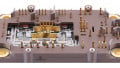
Figure 1: Pictures of experimental wafer layouts investigated. All wafers are cut to 94 mm diameter. Left: HWY layout. Centre: VSW layout. Right: CSW layout
Segment Layout Experiment
The uncertainty around how the outer ring gate would influence the current controllability and gate metallization robustness of an asymmetric device led to extensive simulation (the simulation method is described in [2]) of the impedance characteristics of the gate metallization in such devices. The simulations sparked an experiment investigating three design approaches to segment placement. An early simulation result indicated that the layout has very little influence on the inductive impedance distribution over the wafer, therefore the experimentation focused on the resistive distribution. Figure 1 shows photographs of the initial three designs that are all made up of twelve segment rings containing a varying number of identical segments.
The rightmost photograph shows a variation of a conventional IGCT wafer layout, named “Constant Segment Width” (CSW). As the name suggests, the segment width does not vary with the placement radius and is equal to 250 µm.
The center photograph shows a further refinement of the conventional layout named “Variable Segment Width” (VSW). For this layout variant, the segment width varies with radial placement on the wafer. The VSW concept aimed to help the innermost segments, which have the most disadvantageous placement regarding gate contact, turn off faster by making them narrower. This would compensate for their inherent speed disadvantage given by the later arrival of the gate signal.
A third variant is shown in the leftmost photograph and is named “Highway” (HWY). It is an attempt to avoid loading the approximate outer half of the segment rings with the current generated by the inner half. The HWY concept also features a variable segment width, but the distribution is squeezed together in each of the inner and outer segment ring compartments. The HWY layout allows for a wide range of additional trials: for example, changing the location where the gate metal of the two compartments is connected (if at all). The wafer in the photograph has its inner and outer compartments re-connected after ring ten, something that can be difficult for the untrained eye to make out. A further HWY variant investigated made the gate metallization in the highways, or runners, that connect the inner compartment with the gate contact thicker than in the compartments where the segments are placed.
All three layout variants were manufactured with different gate metal layer thickness, between one and two times the conventional thickness, to decrease the radial ohmic impedance of the gate metal layer. Physical IGCT segment layouts can be quite accurately described by the segment width and spacing distributions over the wafer. The details of the layout variants that were investigated are shown by the graphs in figure 2, which illustrate how the segment width (top graph) and segment-to-segment spacing (bottom graph) vary with segment ring center radius.


Figure 2: Details of the segment layout of the three designs investigated: segment width distribution (a) and segment-to-segment spacing distribution (b).
In addition to the maximum controllable current, the segment layout influences the ruggedness of the cathode contact (on top of the segments). The impact is essentially characterized by the ratio between anode pressed metal area and segment pressed metal area. Ruggedness is clearly improved as the segment packing density increases. The same ratio of metal areas also influences the power loss efficiency, albeit to an extent that is bordering to insignificant.
Results
Power loss trade-off
As a consequence of the slightly different segment packing densities, the variants also display a slight difference in the trade-off between static and dynamic losses. The trade-off between on-state voltage and turn-off losses for a few design variants are plotted in the graph in figure 3.

Figure 3: Technology curve at 4000 A, 2800 V, and Tj 140 °C
Maximal Controllable Current
All variants were tested to destruction in single pulse mode at junction temperatures ranging from 25 °C to 160 °C. The current controllability distributions of the three main variations at VDC 2800 V and Tj 140 °C is shown in figure 4. Clearly, the VSW layout has the highest robustness and, somewhat unexpectedly because the simulations promised a better result, HWY the lowest. A sample waveform of one of the highest switched currents, 8000 A, is plotted in figure 5. At low junction temperatures, there is a clear performance limit due to inductive voltage peaks. The over-voltage is a result of the energy stored in the stray impedance and the rapid current transients pushing the voltage transients close to, or above, the avalanche capability of the device. At low temperatures, this happens at current that, were it not for the over-voltage, would be lower than the device could turn off. Figure 6 shows a turn-off waveform at 25 °C, 6800 A and 2800 V, illustrating this effect. To some extent, the device can clamp the voltage by generating avalanche current, resulting a plateau at the maximal voltage. However, the device would fail in this condition if the energy stored in the stray impedance is too high.


Figure 4: A box-plot showing the distribution of maximum controllable current as tested over the three main layout variants.
Ruggedness at Elevated Temperature and Frequency Operation
Both frequency and HTRB testing demonstrated a device capable of operating with a Tvj, maxwell above the required 140 °C. The frequency test was based on a current chopper setup, with the ability to change the switching frequency, current, voltage, and duty cycle. Thermal failures were provoked at 100 Hz, 4850 A, and 2800 V with a 95% duty cycle. The power losses under such conditions and thermal impedance of the cooling system allowed calculation of the junction temperature (Tvj) to be approximately 230 °C.

Figure 5: A waveform showing one of the events with the highest switched current at Tj 140 °C, IT 8000 A, VDC 2800 V.

Figure 6: Turn-off waveform at 25 °C, 6800 A, 2800 VDC, illustrating the inductive voltage overshoot that exceeds the avalanche capability of the device. The stray impedance for these measurements amounted to Lσ 325 nH.
References
- M. Alexandrova and T. Wikström, “A Technology Platform for Reverse-Conducting Integrated Gate Commutated Thyristors with 94 mm Device Diameter”, in Proceedings of the PCIM, 2017, pp. 806–810.
- T. Wikström, T. Stiasny, M. Rahimo, D. Cottet, and P. Streit, “The Corrugated P-Base IGCT – a New Benchmark for Large Area SOA Scaling”, in Proceedings of the 19th International Symposium on Power Semiconductor Devices and ICs, 2007, pp. 39–32.
This. article originally appeared in the Bodo’s Power Systems magazine.
Related Content