Facebook
 Google
 GitHub
 Linkedin
DC/DC Converters: Circuit Analysis–Intro to Predicting Circuit Output
Circuit analysis is a crucial aspect of understanding implementation and converter output as it involves studying various electrical quantities like node voltages and loop currents through calculations.
The behavior of DC/DC converters is governed by the interaction of components that help build the circuit. Circuit analysis is a key aspect of understanding the implementation and converter output as it involves studying various electrical quantities like node voltages and loop currents through calculations. Read on to learn more about the fundamentals of DC/DC converter circuits and key examples for demonstrating the process of circuit analysis.
Fundamentals of DC/DC Converter Circuits
DC/DC converters form a key aspect of study in power electronics and energy drives in industrial applications. To cater to multiple applications, it is important to implement them based on the requirements and understand the nuances of the circuit behavior [1]. The voltage and current relationships govern the design of converter circuits during equilibrium. Multiple factors influence these values, including voltage ripple in the capacitor, current ripple caused by the inductor, equilibrium state, and so on.
The circuit diagrams of some of the basic DC-DC converters are shown in Figure 1. If we observe these circuits closely, they are mostly composed of basic electrical elements like semiconductor switch, diode, inductor, capacitor, and DC power supply. The arrangement and the quantity of these basic elements differ in these circuits, making them yield different results. The general strategy of circuit analysis is to create and solve a system of independent equations to determine the design conditions or solve for essential variables. It can also be defined as determining the voltages and currents in every element of the circuit [2].
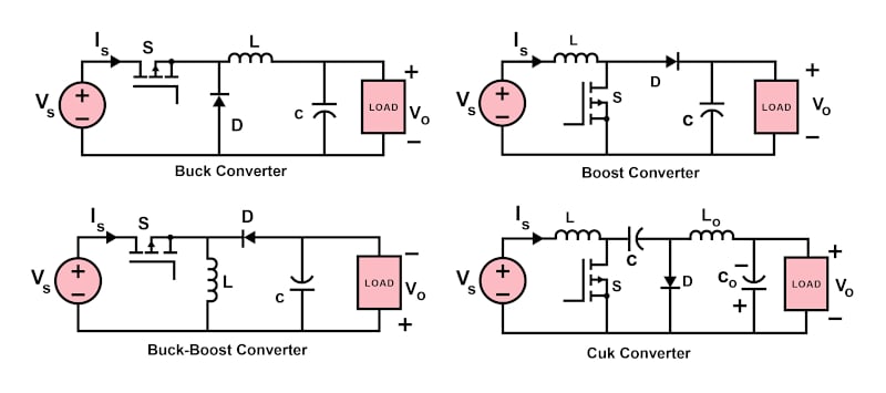
Figure 1. Basic DC-DC converter circuit diagrams. Image property of EETech
Circuit Analysis Example
The operation of DC/DC converters can be distinguished into two distinct modes based on the current flowing through the inductor [3]. When the inductor current is always greater than zero, it is said to be operating in Continuous Conduction Mode (CCM). In the case where the average inductor current is low due to low switching frequency or high-load resistance, the converter is said to be operating in Discontinuous Conduction Mode (DCM).
It is important to know that CCM is the preferred mode of operation for the converters as it offers advantages like improved efficiency, low component count for passive devices, and effective use of semiconductor switches. The converter operation in DCM is slightly more complicated and demands dynamic control. This necessitates determining the minimum value of the inductor so that operation in CCM is maintained.
To simplify the complexity of the circuit analysis, some approximations are made. This includes the assumption that the load is resistive in nature and the DC component of the output voltage is ripple-free. Also, the inductor and capacitor are considered pure in most cases, although it involves a small-ripple approximation.
Consider the example of a buck-boost converter. From Figure 2, it is evident that the polarity of the output voltage is reversed in comparison with the input. Considering that the capacitor is completely charged before the semiconductor switch is turned on, it is evident that the voltage across the switch is equal to the voltage across the inductor once the switch is on. Also, the output voltage is the same as the voltage across the capacitor. Once the switch is off, the voltage across the inductor and capacitor are equal in magnitude but opposite in polarity.
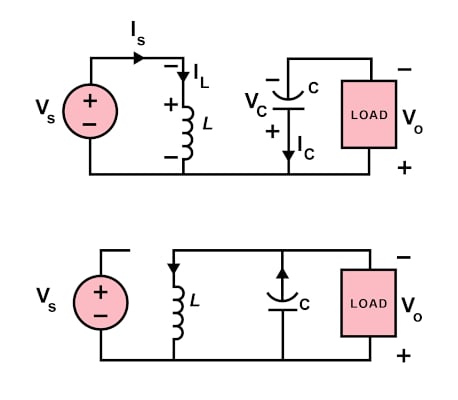
Figure 2. Buck-boost converter circuit diagrams when (a) switch is on and (b) switch is off. Image property of EETech
The key voltage and current waveforms for a buck-boost converter are shown in Figure 3. Observing these closely, the rise in the inductor current when the switch is conducting can be determined by the difference in maximum and minimum values of current. Similarly, when the switch is not conducting, the fall in the inductor current is determined by the difference in values of minimum and maximum inductor currents. This yields the relation between input and output voltages as:
\[V_{O} = D/(1-D).V_{S}\]
where D is the duty cycle.
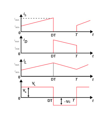
Figure 3. Waveforms of input current, diode current, inductor current, and the voltage across the inductor for a buck-boost converter. Image property of EETech
Further, based on the equation of minimum inductor current and the fact that this value has to be zero to maintain CCM operation, the minimum value of inductance can be estimated. It is important to note that when the duty cycle is less than 0.5, the buck-boost converter acts as a step-down converter, and when the duty cycle is greater than 0.5, it operates as a step-up converter. In the case when the duty cycle is exactly 0.5, the output voltage value is the same as that of the input voltage.
Key Take-aways
- Circuit analysis is a key aspect of understanding the implementation and converter output as it involves studying various electrical quantities like node voltages and loop currents through calculations.
- The general strategy of circuit analysis is to create and solve a system of independent equations to determine the design conditions or solve for essential variables.
- CCM is the preferred mode of operation for the converters as it offers advantages like improved efficiency, low component count for passive devices, and effective use of semiconductor switches.
Key References
1. Fang Lin Luo and Hong Ye, Advanced DC/DC Converters, CRC Press LLC, 2003
3. Rudolf P. Severns and Gordon E. Bloom, Modern DC-to-DC switch-mode power converter circuits, 1985