Facebook
 Google
 GitHub
 Linkedin
DC/DC Converters: Devices Capable of Converting to Higher or Lower Voltage
Buck-Boost converters offer the ability to step-up or step-down the voltage using the same circuit based on the application.
Switch-mode power converters are used extensively in electronics technology across multiple sectors, including industrial, commercial, utility, and consumer markets [1]. For low-power DC/DC conversion-based applications, most modern power conversion is accomplished using three major types of power converters – Buck, Boost, and Buck-Boost.
Buck-Boost converters offer the ability to step-up or step-down the voltage using the same circuit based on the application at hand. Read on to learn more about the basics of Buck-Boost converters and how they work.
Buck-Boost Converter Basics
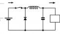
The Buck converter steps down the input voltage, whereas the boost converter steps up the input voltage. Both of these converters serve a specific range of applications. However, some applications require both stepping up and stepping down of the input voltage based on certain conditions or to cater to specific operation scenarios. In such cases, it is not ideal to have two converters housed separately [2]. Thus, a Buck-Boost converter circuit can be utilized as it combines elements of a Buck converter and a Boost converter. The circuit diagram of a Buck-Boost converter is shown in Figure 1.
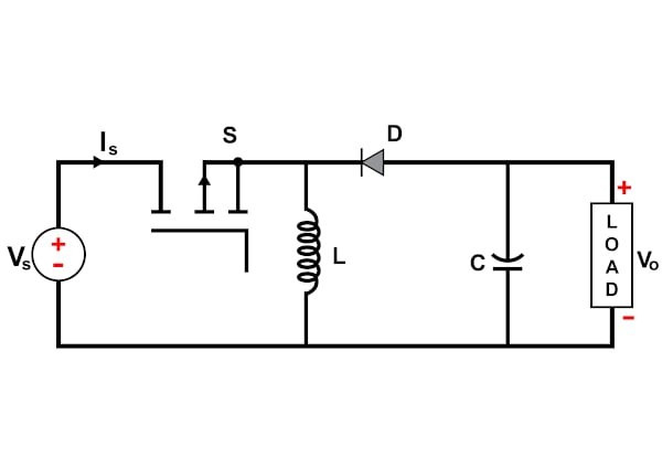
Figure 1. Circuit diagram of a Buck-Boost converter. Image property of EETech
A Buck converter typically regulates the input voltage to a value from zero to a little less than the input voltage. Boost converter, on the other hand, the Boost converter switches the circuit between a mode that stores energy in an inductor while the accompanying capacitor discharges to cater to the output requirement and the mode in which the inductor releases the stored energy to recharge the capacitor while maintaining the overall energy balance. Both of these operations are possible in the case of a conventional Buck-Boost converter. Several variants of the basic converter are available to enable operation at low frequencies and high voltage levels. However, the underlying principle is common for all of them.
In simple terms, a Buck-Boost converter can provide a regulated DC output from a power source that is at a voltage level that is either lesser or greater than the output voltage. Several applications require the capability of modulating the input voltage, including energy storage systems like batteries whose input voltages vary widely. This is because of the charging and discharging cycles of the battery. When the battery is fully charged, the voltage across the battery is typically greater than the required output voltage. In such cases, a Buck converter can be used to maintain a steady supply voltage. Similarly, when the battery is discharging, the voltage level decreases leading to a stage where the battery needs to be recharged to be usable.
High-level Buck-Boost Operating Principle
Buck-Boost converter is known to transform a positive DC voltage at the input side to a negative DC voltage at the output side. The conduction state of the switch dictates the operation of the circuit.
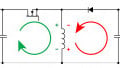
During the on-state, the current flowing through the inductor increases linearly. The diode is not conducting. This is shown in Figure 2. During the off-state, the diode conducts the current and the energy transfer occurs from the inductor to the capacitor. This leads to a reduction of inductor current, although the current through the inductor cannot change abruptly [3]. This is illustrated in Figure 3. It is important to note that energy transfer occurs from the inductor to the capacitor resulting in a voltage across the resistor that is of opposite polarity compared to the input voltage.
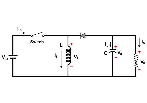
Figure 2. On-state operation of a Buck-Boost converter. Image property of EETech
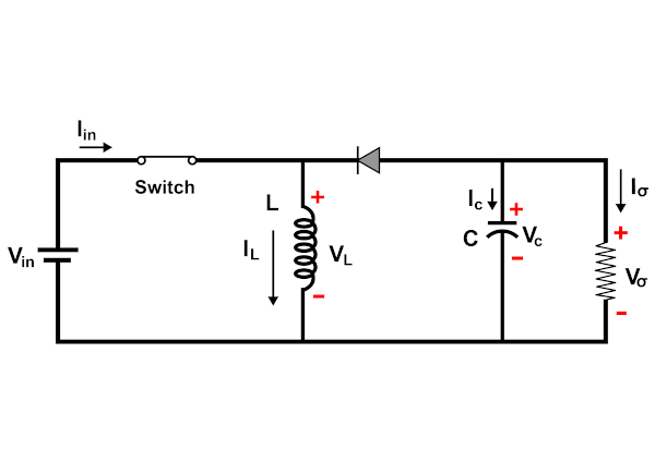
Figure 3. Off-state operation of a Buck-Boost converter. Image property of EETech
During the steady-state operation of the circuit, two modes of operation can be defined based on the inductor current value. If the inductor current never reaches zero, it is termed a continuous conduction mode. However, if the inductor current reaches zero, it operates in discontinuous mode.
The relationship between the input voltage and output voltage for a Buck-Boost converter can be represented by the following equation:
\[V_{out} = -DV_{in}/(1-D)\]
where D is the duty cycle.
The duty cycle is defined as the percentage of the time the switch is turned on. In other words, the parallel combination of inductor and capacitor forms a second-order low-pass filter that smooths out the switching action while producing a clean DC voltage by reducing the voltage ripple.
Key Take-aways
- For low-power DC/DC conversion-based applications, most modern power conversion is accomplished using three major types of power converters - Buck, Boost, and Buck-Boost.
- Buck converters step down the input voltage, whereas boost converters step up the input voltage.
- The relationship between the input voltage and output voltage for a Buck-Boost converter can be represented by the following equation: \(V_{out} = -DV_{in}/(1-D)\).
Key References
1. An Introduction to Buck, Boost, and Buck/Boost Converters