Facebook
 Google
 GitHub
 Linkedin
Data Sheet Factors in Resistor Selection
This article highlights Isabellenhütte about selecting a resistor for applications using data sheets that provide factors that influence the precision, etc.
When selecting a resistor for your application, there is more to bear in mind than you might think. In order to make a preliminary choice using a product datasheet, developers need certain background information and have to calculate some dimensions themselves. An example shows how to correctly use a data sheet.
Basic information
Which resistor is suitable for a current measurement? A quick look in the datasheet is not enough, as there are many factors that influence the precision, temperature dependency and long-term stability. Here, Isabellenhütte gives an introduction to the basic calculation and dimensioning of components.
When measuring current with a resistor, the main parameters that need to be taken into account are the amount of space required, the operating temperature, the dissipation, temperature behaviour, tolerance and the production technology. The datasheet provides important information for perfectly integrating the resistor into the respective application.
The construction, material used and the configuration of the layout can, however, lead to greatly varying results in practical operation. Developers can use the calculations and background information to better understand and use the specifics of the individual parameters and the way they interact. A data sheet may not be a replacement for technical consultation, but it can be a valuable aid when dimensioning the component.
The fundamentals of current measurement
Measuring current using a resistor uses the voltage drop as the direct measurement for the current, as per Ohm’s law. This is no problem with resistance values above 1 Ω and currents of a few hundred mA. The situation changes completely with currents in the range above 10 to 20 A, as the dissipation P = I2 x R generated in the resistor can generally no longer be ignored.
Every developer will try to limit the dissipation with lower resistance values. But as the measurement voltage also decreases simultaneously, the resistance value is often limited by the resolution and quality of the evaluation electronics.
The formula U = R x I generally applies for the voltage measured at the resistor. Factoring in the influences of the component, the material and the construction, however, the formula looks like this:
`U = R * I + U_("th") + U_("ind") + U_("iext")`
Key to symbols:
`U_("th") ": thermoelectric voltage"`
`U_("ind") ": induced voltage"`
`U_("iext") ": voltage drop at supply wires"`
The error voltages not caused by a current flow can heavily distort the measurement result. Their influence should, therefore, be minimised by selecting suitable construction elements and carefully attuning the layout.
Disruptive influences
A resistance value never stands alone, but is always dependent on parameters such as temperature, time, voltage, frequency and others. Table 1 shows the influence of the material shape and production process on the resistor’s measurement signal.
By using optimised amplifier circuits, it is now possible to work with a very low measurement signal. This means that a low-ohm resistance value that leads to a significantly lower dissipation with the same current is sufficient. The component, and therefore the circuit board, are also heated less.

Table 1: influence of material shape and production process.
xxx = large influence
xx = medium influence
x = small but not negligible influence
In addition to the influence of offset, temperature coefficient and noise from operational amplifiers, the resistance values can be lowered to the milliohm range, so that the dissipation P = I2 x R that arises when measuring with a resistor at high currents falls significantly.
Practical example
Using a practical example, such as one that could arise in the automotive sector or industrial drive technology, we can shine a light on which influential parameters are relevant for choosing a suitable resistor. The following factors apply here:
- A current of 17 A is to be measured with high precision.
- A measurement signal of 170 mV is required.
- The component is to be used as an SMD resistor.
The need to measure a current of 17 A and receive a measurement signal of 170 mV results mathematically in a resistance value of 10 mΩ:
`R = U/I = (0.170 "V") / (17 "A") = 0.010 Ω`
Based on this, we can now calculate the dissipation: P = I2 x R gives a dissipation of 2.89 W.
Optimum component size
The maximum operating temperature in the application is required for determining the correct component size. Isabellenhütte data sheets refer here to the contact point temperature in operation. This can be easy to check, with infra-red images able to show the temperature difference here between the hotspot and the contact point. In the datasheet, Isabellenhütte indicates the parameter “internal heat resistance” (abb. Rthi), which describes the heat conductivity of the component design. Using this parameter, it is possible to calculate the temperature increase in the component.
Assuming that P = 2.89 W, a VMS resistor from Isabellenhütte’s VMx series with a power of 3 W can be the component of choice. In the VMS, we now have a temperature increase of 2.89 W x 25 K/W = 72 K. Accord-ing to the datasheet, the VMS delivers the 2.89 W even at a contact point temperature of 98 °C, well above the possible operating temperature of competitor products. Eugen Löwen (Fig. 1), Application Management Sales Components at Isabellenhütte, emphasises: “Isabellenhütte is the technological market leader as far as the component size in relation to dissipation is concerned.
In the industrial sector in particular, however, an evaluation is usually made at a temperature of 70 °C. The calculated increase of 72 K would lead to the component heating up to just 142 °C. With a specified maximum permitted temperature of 170 °C for all Isabellenhütte components, there is still a lot of leeway here.”
Increasing the temperature
In addition to the standard specification P70°C, the Isabellenhütte data sheets also list the temperature at which the component can still perform as specified. In the VMS, for example, this is 3 W at P95°C. These considerations are relevant above all for applications in the automotive sector, where higher temperatures are often involved.
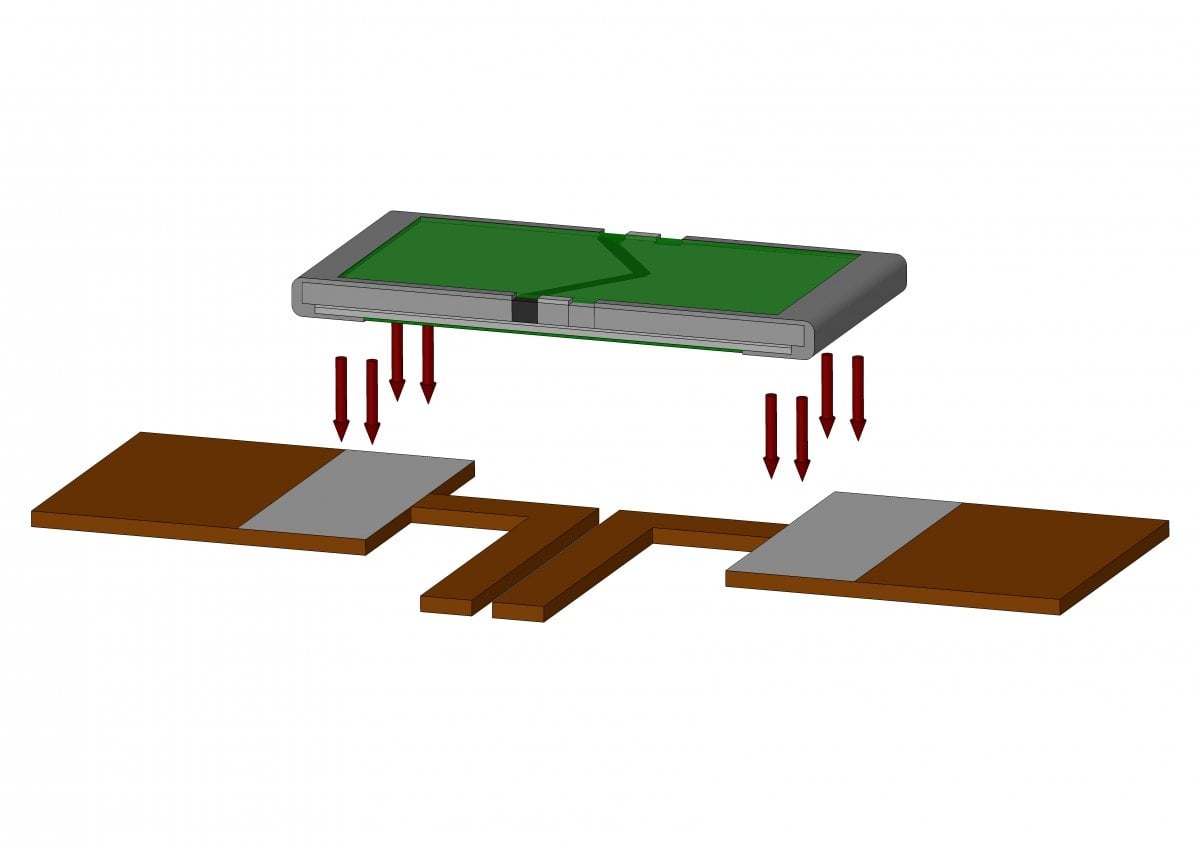
Figure 1: Sensible layout for optimising the temperature coefficient of a measurement resistor.
In the case above, a smaller model can also be used. The specification of dissipation P70°C should also be used here. In the VMP (2010), this is given as 3 W. The 2010 model is therefore easily suitable, even when the VMP, with its 2 W, may not be the obvious choice when the calculated dissipation is 2.89 W. Customers must know the maximum operating temperature of the application. Using the power derating curve in the datasheet, they can determine the maximum temperature of the component at the power level.
In general, reducing the resistance value at higher currents is recommended. In certain circumstances, this allows the use of a smaller and cheaper model. The lower dissipation also means that the system heated up less.

Figure 2: Change in resistance over time in a real SMD resistor operated at 140 °C.
The layout is decisive
The temperature coefficient is determined by the resistance material used. It is possible to manufacture resistors with very high reproducibility. As the measurement has a certain influence on the “2-wire resistance”, however, this can distort the temperature coefficient.
The standard practice in data sheets is to indicate the temperature coefficient of the resistance material used. According to Eugen Löwen, this does not tell us very much: “In our datasheets, we always use the temperature coefficient once soldered in. In our example of the VMS, we can take a very good temperature coefficient of < 20 ppm/K as a basis for the measurement, provided that the customer sticks to the recommended layout. By comparison, the competition can only offer much higher values here.”
Figure 1 shows an example of a sensible layout for improving the temperature coefficient. For calculations using the datasheet, it is vital that the customer uses the specified layout. This is the only way to check the maximum tolerance within the measurement circuit. The temperature behaviour of the component also has an influence on this maximum tolerance. The very good temperature coefficient of < 20 ppm/K can only be achieved when the user complies with the specifications.
The layout also plays an important role in the induction of the component, which is also given in the datasheet. In order to keep this as low as possible, developers should follow the layout in Fig. 3, keeping the two tracks as close to each other on the circuit board as possible so as to avoid loops. This is the best layout for both a small temperature coefficient and for keeping induction as low as possible.
High stability
Another important piece of information in the data-sheet is the long-term stability, which is specified dependent on operating temperature. Generally here the lower the temperature, the lower the drift in the resistance value. The information in the datasheet shows the temperature at the contact point. Inside the component, the temperature caused by dissipation is much higher.
Figure 2 shows the change in resistance in a real SMD resistor as a percentage when the component is operated at 140 °C for 5,000 hours. The low drift of around -0.2 % is caused by resolving the last lattice defects in the resistance material and shows that the components continue to stabilise, i.e. continue to improve.
As the drifts are heavily dependent on the temperature level, this effect almost disappears at 100 °C. In the example given at the beginning, however, users must weigh up the long-term stability in relation to the overall tolerance when selecting a resistor.
In the VMS, which heats up less at the same power, the long-term stability is better than in the VMP, which becomes warmer. “At the end of the day, we often have to find a compromise together with the customer between the size of the component in relation to the right resistor, heating, maximum tolerance and the resulting price”, explains Eugen Löwen: “As all parameters are linked to each other, it is up to the customer to decide which requirements are most important. This helps us find the right component.”
About the Author
Dipl.-Ing. Thomas Otto worked as technical sales and distribution at Isabellenhütte that is a wholly-owned subsidiary of Isabellenhütte Heusler GmbH KG, located in Dillenburg, Germany. Formed in 1989, Isabellenhütte USA is a leading supplier of precision current sensing and high power resistors, thermo electric and resistance alloys, and precision measurement systems. Located in Swansea MA, we have developed an industry-wide reputation for providing high-quality products and unparalleled customer support. Backed by decades of manufacturing and engineering expertise, and a representative network that spans all of North America, Mexico, and Brazil, our mission is to provide superior resistive solutions into the automotive, industrial and aerospace industries.
This article originally appeared in the Bodo’s Power Systems magazine.