Facebook
 Google
 GitHub
 Linkedin
Causes and Solutions of the Potential Induced Degradation (PID) Effect in PV Modules
In case you are dealing with unexpected and unreasonable power loss in your photovoltaic plant, you may be experiencing the PID effect in the PV modules.
Potential induced degradation (PID) is a phenomenon that arises over time (months or even years). It may be negligible in the plant’s early stage but, over time, becomes more noticeable in advanced phases, causing important power losses. However, it’s not always easy to determine the main cause.
Where Does PID Occur in PV Modules?
PID is related to the negative potential that each PV module can deal with when working in normal operative conditions. PV modules are connected in series to create a string and the overall string voltage is distributed among all the single PV modules. How this voltage distribution happens depends on the inverter type used.
For example in case of a 1000V DC system we can have the following simple classification:
Transformerless inverter: Typically the voltage is distributed symmetrically -500V … + 500V but it depends on the inverter type because, in some cases, it’s common to have an offset more in the negative side (for example -700V … + 300 V).
Inverter with galvanic isolation: The voltage is distributed in a symmetrical way -500V…+500V.
Inverter with galvanic isolation with one pole grounded: In this case, the voltage distribution will be 0V…+1000V if the positive pole is grounded, or -1000V...0V if the negative pole is grounded.
In these voltage distributions, considering a 1000 V DC system, each PV module has about 50V of voltage across its terminals.
As said above, the PID effect is linked to the negative potential of each PV module, so the higher the negative voltage is in the overall voltage distribution, the higher the probability to experience this effect. Let’s focus on how it works actually.
Potential Induced Degradation Explained
A PV module is made by several components (Figure 1), but the ones that play an important role in this discussion are the solar cell, the encapsulant material (EVA in most of the cases), and the aluminum frame.
_Effect_In_Pv_Modules_Figure_1.jpg)
Figure 1. PV module composition. Image courtesy of PV Education.
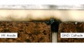
When a solar cell is polarized with a high negative voltage, there is a relevant voltage difference between the cell itself and the module frame. This is at zero potential because most of the time it is grounded, so, due to the very short distance between solar cells and frame and due to possible presence of impurities in the encapsulant material, a current can be created between the cells and the frame, generating a current leakage for the entire PV module.
_Effect_In_Pv_Modules_Figure_2.jpg)
Figure 2. Possible leakage current path. Image courtesy of Fraunhofer.
Let’s look at an example to better explain the effect. Suppose we have a transformerless inverter with symmetrical distribution at 1000V DC.
The voltage distribution on the string will be like the one shown in Figure 3.
_Effect_In_Pv_Modules_Figure_3.jpg)
Figure 3. Example of voltage distribution in the string connected to a transformerless inverter at 1000V DC system.
The PV module that falls in the more negative section of the string will be the most affected by this effect because its cells would be polarized at around -500V while the frame of the module is at 0 potential (because it is grounded). So, there is a very high potential difference that can create a leakage current from the cells to the ground. Once the effect takes place, it becomes more evident with time and the leakage current will keep increasing.
How to Detect PID in a PV Module
To determine if a PV module is affected by PID, it’s possible to perform an I-V curve test or an electroluminescence test. Note that the electroluminescence test only indicates if some cells are underperforming without giving any relevant indication about the causes.
The I-V curve test is more appropriate in this case due to the nature of the PID effect. PID reduces the performance of the PV modules due to a reduction in the shunt resistance of the electrical model (Figure 4). This corresponds to an increase in the leakage current, resulting in a decrease of the output current (and so, total output capacity) and affects the I-V curve as shown in Figure 5.
_Effect_In_Pv_Modules_Figure_4.jpg)
Figure 4. One-diode model of a PV module. Image courtesy of Sandia.
_Effect_In_Pv_Modules_Figure_5.jpg)
Figure 5. I-V curve comparison between PV module affected by PID and not affected by PID. Image recreated from Caroline Bedin.
Mitigation Actions
Luckily, in most cases, the PID effect is reversible. However, if it has existed for a prolonged time without measures taken to fix the problem, it will permanently affect the cells and the encapsulant intrinsic properties.
If PID has taken place, it can be mitigated by grounding the negative DC pole on the inverter in order to avoid negative voltages on the strings. This works if the inverter allows this operation mode and all the proper design action associated with this choice is taken.
PID can also be mitigated by using a so-called “anti-PID box” that is installed between the strings and the inverter. The anti-PID box reverses the potential applied by the inverter in order to polarize all of the PV modules that were affected by the negative voltage in the opposite way. These boxes work to avoid each string from keeping the same polarization for too much time in order to reduce the probability of PID and giving each module the possibility to “recover” the negative potential suffered.
PID Prevention Actions
In the case of new PV plants, it’s important to focus attention on the type of materials and the design choice of each module before making any purchases.
Design choices that can affect the occurrence of PID are mainly related to PV module choice. For example, choosing a frameless PV module reduces the probability of PID because the region at zero potential would be very minor compared to a frame module. Only a small portion of the clamps dimension will have ground potential. There will also be additional insulating material between the clamp and PV modules, so a possible leakage current would have less probability of appearing.
On the other hand, frameless modules are typically double glass with a higher weight and they cost a bit more, so they’re not always the best choice for all projects. Generally, it’s possible to focus on the quality of the PV module and its bill of materials before purchasing. In this sense, the IEC standard provides support on the required quality.
There is a specific standard family — IEC 62804 Photovoltaic (PV) modules: Test methods for the detection of potential-induced degradation — that aims to detect the potential induced degradation in the early life of PV modules by testing products under extreme conditions that represent an acceleration of the PV module lifetime.
Once PV module manufacturers get their products certified for the IEC 62804 family, they usually add the label “PID free” to their product. Unfortunately, this label does not guarantee that PID won’t take place, and with the current technology, completely PID free modules don’t exist. Let’s have a look at the meaning of this certification to better understand why.
The test conditions to detect the potential induced degradation according to the IEC 62084 are:
-
60°C air temperature
-
85% relative humidity
-
voltage biases of +1000 V, -1000 V, +1500 V, or -1500 V (according to the PV module characteristics)
-
total test duration of 96 hours
The pass criteria are mainly related to the power degradation measured at the end of the test. If it does not exceed 5%, the test has been passed. So, the test does not ensure that PID won’t happen or that a module is PID free, it just measures the power degradation after operation under specific extreme conditions for a defined time period.
However, it is possible to take results from the certification that each manufacturer can provide. PV modules with lower power degradation in the IEC 62804 certification would probably be the most resistant to the PID effect when compared to other PV modules with higher power degradation. It’s also worth saying that some manufacturers are starting to perform the certification with increased time duration (up to 600 hours) and a similar certification would be reliable for obtaining a product with strong resistance to the PID effect.