 Facebook
 Google
 GitHub
 Linkedin
Calculating Force on Current-carrying Conductors
In this article, learn how to calculate the force exerted on a current-carrying conductor situated in a magnetic field and define the direction of the force. Also, learn how to calculate the torque exerted on a coil pivoted in a magnetic field.
When a current-carrying conductor is placed in a magnetic field, it experiences a force due to the interaction between the conductor and field flux. The magnitude of the force on a current-carrying conductor in a magnetic field is proportional to the current, the flux density of the field, and the length of the conductor within the field. It is measured in newtons (N).
Force on a Conductor
Figure 1(a) shows an end view of a current-carrying conductor in a magnetic field. With the current direction as indicated by the +sign (i.e., away from the viewer), the flux set up by the current is in a clockwise direction around the conductor. When the field flux has the vertically downward direction indicated, the flux from the conductor tends to assist the field flux on the right-hand side of the conductor. The conductor flux also opposes (or weakens) the field flux on the left-hand side of the conductor. Because the magnetic lines of force always tend to be in tension, those lines of force on the right-hand side of the conductor tend to straighten out. This results in a force pushing the conductor to the left.
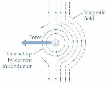
(a) Conductor current flowing away from the viewer.
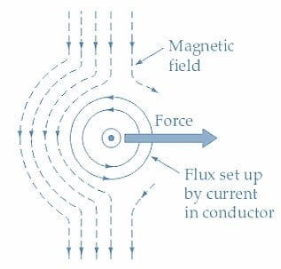
(b) Conductor current flowing toward the viewer.
Figure 1. A current-carrying conductor situated in a magnetic field experiences a force due to the interaction of the conductor flux and the field flux. The conductor flux reinforces the field flux on one side of the conductor and weakens it on the other side. Image used courtesy of Amna Ahmad
When the current direction is reversed, as illustrated in Figure 1(b), the flux around the conductor is in a counterclockwise direction. So, the field flux is assisted on the left-hand side of the conductor and weakened on its right side. The result is a force that pushes the conductor to the right.
The effect is further illustrated in Figure 2, where the field flux is shown vertically downward. The current direction is such that the field set up around the conductor weakens the main field in front of the conductor and strengthens it behind the conductor. The result, as illustrated, is that a force acts to push the conductor forward. Note that the conductor must be at right angles to the direction of the magnetic flux, otherwise, maximum force is not generated.
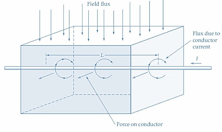
Figure 2. The force on a current-carrying conductor in a magnetic field is proportional to the current, the field's flux density, and the conductor's length within the field. Image used courtesy of Amna Ahmad
The magnitude of the force on a current-carrying conductor in a magnetic field is equal to the flux density of the field and the density of the flux set up by the conductor. Because the flux set up around the conductor is directly proportional to the current, the force on the conductor is proportional to the current and the flux density of the magnetic field. If a 2 m length of conductor is within the magnetic field, the force exerted on it is twice the force that would be exerted on a 1 m length. So, the force on the conductor is seen to be proportional to the length of the conductor within the field, the field flux density, and the current carried by the conductor. Therefore,
Force on Conductor = Field Flux Density ×Current ×Length
Or
\[F=BIl\] (1)
When B is in teslas, I is in amperes, and l is in meters, the force F is given in newtons (N). So, a force of 1 N is exerted on a 1 m length of a conductor carrying a current of 1 A and situated in a magnetic field having a flux density of 1 T.
Example 1
A conductor carrying a current of 15 A is located at right angles to a magnetic field with a flux density of 0.7 T (see Figure 2). Determine the force exerted on the conductor if its length within the field is 20 cm. Also, determine the new value of current that will be required to increase the force to 25 N.
Solution
From Equation 1
\[F=BIl=0.7T\times15A\times20\times10^{-2}m=2.1N\]
\[I=\frac{F}{Bl}=\frac{25N}{0.7T\times20\times10^{-2}m}=179\,A\]
Force on a Coil
In Figure 3(a), a single-turn coil is shown pivoted in the magnetic field set up by N and S poles. Consideration of the current direction through the coil shows that there is a downward force on its left-hand side and an upward force on its right-hand side [see Figure 3(b)]. The coil length within the magnetic field is l meters, and (from Equation 1) the force on each side of the coil is
\[F=BIl\]
For a coil with N turns
\[F=BIlN\]
Because the force acts at a radius (r), there is a torque on each side of the coil.
\[torque\,on\,each\,side=F\times r=BIlNr\]
With B in teslas, I in amperes, l in meters, and r in meters, the torque is expressed in joules (J). For the two sides of the coil, the total torque is,
\[Total\,Torque=2BIlNr\]
The coil diameter D equals 2 r. So
\[Total\,Torque=BIlND\] (2)
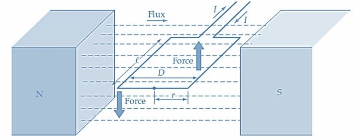
(a) Single-turn coil positioned in a magnetic field
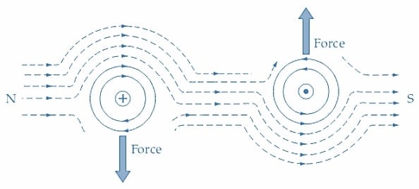
(b) Showing the force on each side of a single-turn coil pivoted in a magnetic field
Figure 3. When a coil is positioned in a magnetic field, force is exerted on each side of a current-carrying coil. As a result of this force, the coil rotates. Image used courtesy of Amna Ahmad
Example 2. Calculate the torque acting on a 100-turn coil pivoted in a magnetic field having a flux density of 0.5 T. The current through the coil is 100 mA, its radius is 1 cm, and its axial length is 2 cm.
Solution
From equation 2
Total Torque=BIlND=0.5T ×100 mA ×2 × 10-2 ×100 ×2 × 10-2=2 × 10⁻³ J
Takeaways of Current-carrying Conductors
An electric current through a conductor generates a magnetic field around the conductor. If the conductor is placed in an external magnetic field, a force is created due to how the magnetic field generated by the current and the external magnetic field interact. The force experienced by the conductor is determined by the formula
F = BIL
where F is the force, B is the strength of the external magnetic field, I is the current flowing through the conductor, and L is the length of the conductor in the direction of the magnetic field.
Similarly, when an electric current flows through a coil of N turns, it creates a magnetic field. The force experienced by a current-carrying coil in an external magnetic field is known as the electromagnetic force.
The force on a coil can be calculated using the formula
F = BILN
where F is the force, N is the number of turns in the coil, I is the current flowing through the coil, and B is the strength of the external magnetic field.
Featured image used courtesy of Adobe Stock


So when a motor turns it not only turns so that it’s electronically charged polls align with the respective fields to which they are attracted, but also as a result of the force generated by the magnetic flux in the current carrying conductors?
Good article, thanks. There is a typo error in the equation above Fig. 3a: Should be “Total Torque = BIlND”, not “Total Torque = BIlBD”.