Facebook
 Google
 GitHub
 Linkedin
Calculating Conductor Ampacity to Carry Motor Current
Learn to compute the ampacity and size of circuit conductors for motors rated 1 kV or less.
Inrush current makes the conductors for motor circuits a particular case. Part II of NEC (National Electrical Code) Article 430 comprises rules to compute the ampacity of the branch-circuit conductors for various types and combinations of electric motors and non-motor loads. Section 430.6(A)(1) requires finding the motor full-load current from NEC tables instead of using the nameplate data for general motor installations.
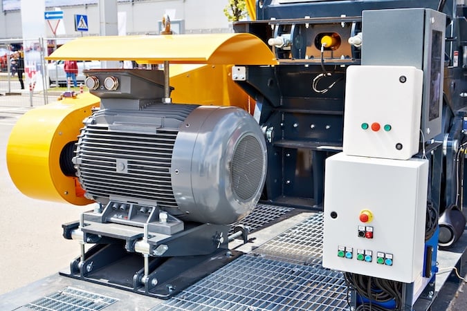
Image used courtesy of Adobe Stock
Part II Motor Circuit Conductors
Part II applies to motor circuits rated 1000 V or less.
National Electrical Code Section 430.21 General
Compute the motor conductor ampacity according to Part II to avoid overheating with the motor used under the specified conditions.
NEC Section 430.22 Single Motor
Branch-circuit conductors supplying a single motor in a continuous duty application shall have an ampacity equal to or higher than 125% of the motor full-load current rating per Section 430.6(A)(1) or not less than stated in sections 430.22(A) through (G).
- Establish the motor full-load current (FLC) rating per Section 430.6(A)(1). Use tables 430.247, 430.248, 430.249, and 430.250, depending on the motor characteristics.
- Do not use motor nameplate FLC to size the branch-circuit conductors.
Following this requirement, the motor will not load the conductors above 80% of its rating except for the short period of the inrush current.
The main disadvantage of squirrel-cage induction motors is the high starting current. Although there are some exceptions among the various classifications of commercial squirrel cage induction motors, they typically require four to six times their rated current to start with the rated voltage applied to their stator.
As the inrush period is brief, there is no need to size the conductor to such an amount of current. Sizing the motor circuit conductor to 125% of the full-load current rating will easily accommodate the additional heat created into it.
This rule applies to all motors in tables 430.247, 248, 249, and 250.
The 125% factor is unrelated to the 125% factor employed to compute the conductor size for the overcurrent device termination. Do not apply both factors simultaneously when selecting the conductor size because the percentage would be 125% x 125% = 156%, which is not an NEC requirement.
- Select the conductor size from Table 310.16, acknowledging the terminal temperature rating of the equipment – 60°C or 75°C – per Section 110.14(C)(1 ).
Example 1: Find the size of the branch-circuit THW conductors of the 230-V, 3-phase, 5-hp, squirrel-cage motor shown in Figure 1.
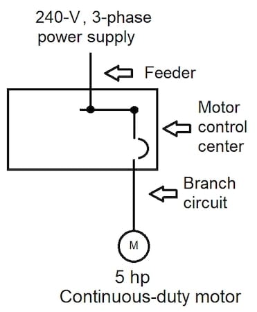
Figure 1. Set-up for Example 1. Image used courtesy of Lorenzo Mari
Solution:
Enter Table 430.250 with 5 hp and read FLC = 15.2 A in the 230-V column
Multiply the FLC by 125%
15.2 A x 1.25 = 19 A
Enter Table 310.16 in the 75°C (THW) column. Conductor size N° 14 AWG has an allowable ampacity of 20 A.
Select conductor size N° 14 AWG
Section 430.22(A) DC Motor-Rectifier Supplied
A DC motor drive controller with an AC voltage input includes a rectifier circuit to change AC to DC. The rectifier commonly utilizes diodes or thyristors to guide the current in one direction.
Select the conductor ampacity on the rectifier’s input at least 125% of the rectifier’s rated input current.
The ampacity of the conductors between the motor and the field wiring output terminals of the rectifier, for DC motors operating from a rectified single-phase power supply, must be not less than the following percentages of the motor full-load current rating:
- 190% for half-wave type.
- 150% for full-wave type.
Section 430.22(B) Multispeed Motor
Multispeed motors run at two or more speeds, with two-speed motors being more common. Different winding connections to the source change the speed.
- Base the branch-circuit conductor size on the line side of the controller on the highest of the full-load current ratings marked on the nameplate.
- Select the ampacity of the branch-circuit conductors between the controller and the motor as 125% of the current rating of the winding(s) supplied by the conductors as a minimum.
Example 2: The multispeed motor in Figure 2 shows the following full-load current data on its nameplate: 1725 RPM, 46 A; 2300 RPM, 36 A; 3450 RPM, 28 A. Find the minimum size of the branch-circuit THW copper conductors a. on the line side of the controller. b. between the controller and the motor.
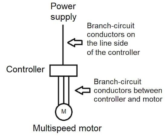
Figure 2. Set-up for Example 2. Image used courtesy of Lorenzo Mari
Solution:
a.
Highest full-load current rating = 46 A
46 A x 1.25 = 57.5 A
From Table 310.16, 75° column, conductor N° 6 AWG has an ampacity of 65 A
Use conductors N° 6 AWG THW
b.
1725 RPM use conductors N° 6 AWG THW
2300 RPM
36 A x 1.25 = 43.2 A
From Table 310.16, 75° column, conductor N° 8 AWG has an ampacity of 50 A
Use conductors N° 8 AWG THW
3450 RPM
28 A x 1.25 = 35 A
From Table 310.16, 75° column, conductor N° 10 AWG has an ampacity of 35 A
Use conductors N° 10 AWG THW
Section 430.22(C) Wye-Start, Delta-Run Motor
A Wye-Start, Delta-Run motor starts with the primary winding connected to the wye and then changes to delta for run operation. This method reduces the motor’s starting current.
The starting voltage is 1/√3 of the phase-to-phase voltage, reducing the starting current and torque by a factor of 3.
- Size the branch-circuit conductor on the line side of the controller for 125% of the motor FLC rating as required in Section 430.6(A)(1), as a minimum.
- Size the branch-circuit conductor from the controller to the motor for 72% of the motor FLC rating as required in Section 430.6(A)(1), as a minimum.
The current in the delta windings equals 1/√3 of the FLC rating. Applying the same 125% factor, 1/√3 x 1.25 = 72%.
Section 430.22(D) Part-Winding Motor
A part-winding motor starts by energizing a section of its primary winding and then energizing the remainder in one or more steps.
Size the branch-circuit conductor on the line side of the controller for 125% of the motor FLC rating as required in Section 430.6(A)(1), as a minimum.
Size the branch-circuit conductor from the controller to the motor for 62.5% of the motor FLC rating as required in Section 430.6(A)(1), as a minimum.
The phase windings are connected in parallel, each carrying 50% of the FLC rating. Applying the same 125% factor, 50% x 1.25 = 62.5%.
Example 3: Figure 3 shows the wiring diagram of a 230-V, 40-hp, squirrel-cage, part-winding start induction motor. Find the minimum size of the THW copper conductors a. on the line side of the controller. b. between the controller and the motor.
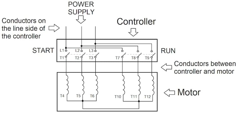
Figure 3. Set-up for Example 3. Image used courtesy of Lorenzo Mari
Solution:
From Table 430-250, 230-V column, a 40-hp motor has an FLC = 104 A
a.
104 A x 1.25 = 130 A
From Table 310.16, 75° column, conductor N° 1 AWG has an ampacity of 130 A
Use conductors N° 1 AWG THW
a.
104 A x 0.625 = 65 A
From Table 310.16, 75° column, conductor N° 6 AWG has an ampacity of 65 A
Use conductors N° 6 AWG THW
Section 430.22(E) Other Than Continuous Duty
This section categorizes four types of motor duty-cycle applications: short-time duty, intermittent duty, periodic duty, and varying duty.
- Set the ampacity of the conductors used in motors for these four types of applications at not less than the percentage shown in NEC Table 430.22(E) times the motor nameplate current.
The authority having jurisdiction may grant special permission to use conductors of lower ampacity.
Due to the periodic inrush currents, noncontinuous applications may generate more or less heat than continuous operation, depending on the service. The percentages listed in Table 430.22(E) consider this fact.
The figures in Table 430.22(E) depend on the service classification and whether the motor is rated 5-, 15-, 30-, or 60-minute. There is also a column for continuous-rated motors.
The branch-circuit conductors supplying lower-rated motors have larger cooling intervals between the operating periods. The conductors can be smaller than those for motors of the same horsepower but with higher ratings.
Example 4: Find the size of the branch-circuit THW conductors of a 208-V, 3-phase, 15-hp, squirrel-cage motor used for intermittent duty, rated for 30-minute service. Nameplate full-load current = 46 A.
Solution:
Enter Table 430.22(E), intermittent service, and read 90% under the 30-minute rated motor column.
Multiply the FLC by 90%.
46 A x 0.9 = 41.4 A
Enter Table 310.16 in the 75°C (THW) column. Conductor size N° 8 AWG has an allowable ampacity of 50 A.
Select conductor size N° 8 AWG THW
Section 430.22(G) Conductors for Small Motors
This section rules the minimum conductor size for small motors to N° 14 AWG unless permitted in sections 430.22(G)(1) or (G)(2).
Sections 430.22(G)(1) and (2) permit the use of copper conductor sizes N° 18 AWG and N° 16 AWG under a set of conditions. These conditions limit the type of conductors or their location. The conditions also specify the overcurrent protection characteristics based on the motor full-load current rating.
NEC Section 430.24 Several Motors or Motors and Other Loads
This section covers the condition where the conductors supply two or more motors or motors and other loads. An example is feeder conductors to a motor control center and a 15- or 20-A branch circuit supplying motors, lighting, or appliance loads.
The NEC requires making a few calculations and adding them later. The result is the lowest circuit conductors’ ampacity. The procedure assumes that the maximum current the feeder will see is the largest motor start, with the other motors and non-motor loads operating normally.
The method is as follows:
Step 1: Get the following data:
a. Full-load current rating of all motors, per 430.6(A)
b. Noncontinuous non-motor load
c. Continuous non-motor load
Step 2: Multiply the full-load current rating of the highest-rated motor by 1.25.
Step 3: Add the full-load current ratings of the other motors.
Step 4: Multiply the continuous non-motor load by 1.25.
Step 5: Sum the results of steps 2, 3, and 4 to the noncontinuous non-motor load.
Example 5: What is the lowest circuit conductors’ ampacity allowed for a feeder supplying one 208-V, 3-phase, 3-hp motor and one 208-V, single-phase, 2-hp motor?
Solution:
Step 1: From Table 430.250 FLC 3-hp motor = 10.6 A
From table 430.248 FLC 2-hp motor = 13.2 A
Step 2: Highest FLC 13.2 A x 1.25 = 16.5 A
Step 3: 10.6 A
Step 4: 0 A
Step 5: 16.5 A + 10.6 A = 27.1 A
The lowest ampacity allowed = 27.1 A
Note that we multiply the highest FLC by 1.25, not the FLC of the highest hp motor. We protect the conductor from heat, and the current creates heat.
Example 6: What is the minimum size THHN feeder conductor allowed in example 5?
Solution: Enter Table 310.16 in the 90°C (THHN) column. Conductor size N° 12 AWG has an allowable ampacity of 30 A.
Select conductor size N° 12 AWG THHN
Example 7: What is the lowest circuit conductors’ ampacity allowed for a feeder supplying one motor with an FLC = 10 A and one noncontinuous heat load of 15 A?
Solution:
Step 1: Motor FLC = 10 A. Noncontinuous heat load = 15 A
Step 2: 10 A x 1.25 = 12.5 A
Step 3: 0 A
Step 4: 0 A
Step 5: 12.5 A + 15 A = 27.5 A
Lowest ampacity allowed = 27.5 A
Example 8: Repeat Example 7 with a continuous heat load of 15 A
Solution:
Step 1: Motor FLC = 10 A. Continuous heat load = 15 A
Step 2: 10 A x 1.25 = 12.5 A
Step 3: 0 A
Step 4: 15 A x 1.25 = 18.75 A
Step 5: 12.5 A + 18.75 A = 31.25 A
The lowest ampacity allowed = 31.25 A
Example 9: What is the minimum size THHN feeder conductor allowed in example 7?
Solution: Enter Table 310.16 in the 90°C (THHN) column. Conductor size N° 12 AWG has an allowable ampacity of 30 A.
Select conductor size N° 12 AWG THHN.
Example 10: What is the minimum size THHN feeder conductor allowed in example 8?
Solution: Enter Table 310.16 in the 90°C (THHN) column. Conductor size N° 10 AWG has an allowable ampacity of 40 A.
Select conductor size N° 10 AWG THHN.
Note the increase in conductor size when the heat load is continuous. The reason is that the noncontinuous non-motor loads don’t continually heat the conductors, but the continuous non-motor loads do.
Example 11: Figure 4 shows an industrial plant’s three motors and a lighting load. The motors are 460-V, 3-phase, general-purpose, squirrel-cage, and continuous duty. Find a. minimum THW conductor size for the feeder. b. minimum THW conductor size for the four branch circuits.
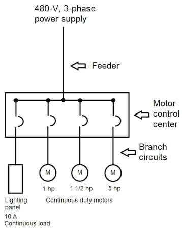
Figure 4. Set-up for Example 11. Image used courtesy of Lorenzo Mari
Solution:
a. First, find the lowest circuit conductors’ ampacity.
Step 1: FLC taken from Table 430.250: 1-hp motor = 2.1 A; 1½-hp motor = 3.0 A; 5-hp motor = 7.6 A
Continuous lighting load = 10 A
Step 2: 7.6 A x 1.25 = 9.5 A
Step 3: 2.1 A + 3.0 A = 5.1 A
Step 4: 10 A x 1.25 = 12.5 A
Step 5: 9.5 A + 5.1 A + 12.5 A = 27.1 A
The lowest ampacity allowed for the feeder = 27.1 A
Second, enter Table 310.16 in the 75°C (THW) column. Conductor size N° 10 AWG has an allowable ampacity of 35 A.
Select conductor size N° 10 AWG THW
b.
Minimum ampacity 1-hp motor = 2.1 A x 1.25 = 2.63 A
Minimum ampacity 1½ -hp motor = 3.0 x 1.25 = 3.75 A
Minimum ampacity 5-hp motor = 7.6 x 1.25 = 9.5 A
Minimum ampacity continuous lighting load = 10 A x 1.25 = 12.5 A
Section 430.22(G) requires a minimum size of N° 14 AWG for small motors. The ampacity of conductor N° 14 AWG THW = 20 A.
Sections 430.22(G)(1) and (2) permit the use of sizes N° 18 AWG and N° 16 AWG under a set of conditions. However, Table 310.16 does not include ampacities for THW conductors in these sizes. A similar situation arises with the branch circuit for the lighting load.
In conclusion, use conductor size N° 14 AWG THW for the four branch circuits.
Choosing the Correct Conductor Ampacity Takeaways
- An electric current produces heat, and the conductors must be able to dissipate it without suffering any damage.
- “Ampacity” is the maximum current a conductor can transport without surpassing its temperature rating.
- The inrush currents require special attention when selecting conductors for motor circuits.
- Part II of NEC’s Article 430 directs how to determine the ampacity required in motor circuits.
- The ampacity of a motor system’s branch-circuit and feeder-circuit conductors is established based on the motor and non-motor loads’ characteristics and arrangement.