Facebook
 Google
 GitHub
 Linkedin
A Practical Study on Three-Level Hybrid SiC/Si Inverters
This article highlights Infineon Technologies Italia S.r.l - Austria AG demonstration of the use of SiC devices that allows high degree of freedom in design.
In today’s PV, UPS and GPI systems, three-phase output inverters are often based on three-level topologies using Silicon IGBTs. This article demonstrates the potential of a hybrid inverter using CoolSiCTM MOSFETs and TRENCHSTOPTM 5 Silicon IGBTs.
State of the Art Three-Level Inverter Topologies
Three-level inverters based on Silicon IGBTs are a common design solution giving an excellent cost/performance ratio. As explained in [1]-[3], the technical advantage over the classical two-level B6 inverter represented in Figure 1 (a) is a reduction of switching losses and filtering effort, at the expenses of higher circuit complexity. Two commonly found three-level designs in the low to mid-power range are the Neutral Point Clamping Diode and the Neutral Point Clamping Transistor topology, illustrated in figure 1 (b) and (c), respectively.


Figure 1: Commonly used inverter configurations: (a) two-level (B6, Six-Pack) inverter; (b) three-level neutral point clamping diodes (NPC-1, I-Type) inverter; (c) three-level transistor clamped (NPC-2, T-Type) inverter; for each topology, only one out of three phases is shown.
As explained in [2], [4] and [5], both three-level topologies have their advantages and disadvantages. While T-Type inverters have fewer semiconductor devices on the current path and thus low conduction losses, I-Type inverters benefit from lower switching losses as there is no need for a relatively slow higher voltage device. Consequently, T-Type inverters are typically found at switching frequencies up to 20-30kHz, I-Type inverters above.
SiC Technology Changes the Picture
The unique features of Silicon Carbide (SiC) switches were described in [7] and [8] together with the potential impact on applications. With the emerging SiC semiconductor technology the degrees of freedom for the designer become higher, opening the path to new scenarios: fast 1200V SiC switches can make T-Type inverters attractive for higher frequencies and even the transition back to a two-level solution might be considered in order to achieve higher efficiency and reduce the bill of material [6].
In the following sections, the potential of a hybrid T-Type inverter using 1200V CoolSiC™ MOSFETs and 650V TRENCHSTOPTM 5 IGBTs is demonstrated experimentally. The key benefits of this approach are low conduction and switching losses, relatively low effort for output and EMI filtering and – compared to converters with more than three levels – moderate control effort.
Test Setup and Conditions
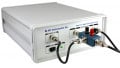
Since this article considers the influence of only the power semiconductors on the system efficiency, all measurements were carried out using a single-phase test board and a fixed L-C-L output filter designed by Tecnologie Future S.r.l. and Infineon Technologies Austria A.G. The design goals for this platform were a simple component replacement as well as an easy access for thermal and electrical measurements – not a demonstration of power density or a BOM cost reduction.
It should be noted that the absolute efficiency values obtained with a single-phase system do not correspond one-to-one to the values of a three-phase and three-wire system, i.e. a system without exposed neutral. First, the core losses of the filters are different and second, the modulation scheme cannot use a third-harmonic injection technique.
All devices were operated using an Infineon 1EDI60N12AF driver. This compact, isolated, single-channel driver is based on the coreless transformer technology, featuring a high common mode transient immunity – a major requirement when dealing with high speed switches. The output voltage of the drivers is provided using a local HF transformer close to the driver that is fed from one resonant AC link. Using the turn-ratio of the transformer, the gate voltages are set to +15V for turn-on and -5V for turn-off.
The single-phase inverter was operated at a constant DC link voltage of 720VDC providing a voltage of 230VRMS on the output. Using an electric AC load the output current of the inverter was increased in steps of 1,5ARMS every 5 minutes in order to determine the conversion efficiency for different load situations.


Figure 2: Single-phase test platforms in front and side view
Test results
A summary of all measurement results can be found in Table 1. For each scenario, the circuit, the devices under test, the switching frequency fsw as well as the maximum achievable output power Pmax and efficiency ηmax are given.
Figure 3 shows the conversion efficiency levels obtained as a function of the output power at 24kHz and 48kHz, respectively. The efficiency values consider the losses on the semiconductors and passives but not the power required for control and driving.
The loss distribution depicted in Figure 4 was estimated with an analytic calculation routine and verified using chip and heat sink temperatures. Minor deviations were considered to be caused by a deviation of switching losses and corrected according to the experimental data. Calibration measurements to determine the correlation of losses and temperatures were done upfront.
The selection of the 1200V devices is based on the DC current rating of the datasheet. The 650V switches were kept the same throughout all tests: S5 IGBTs with a trade-off of conduction and switching losses. For the diode, a fast Si diode as well as a SiC SBD – both with the same DC current rating at 100°C case temperature – were selected.

Table 1: Test scenarios and results for the single-phase test system at unity power factor


Figure 3: Conversion efficiency as a function of output power for the single-phase test system at unity power factor

Figure 4: Distribution of the semiconductor losses in the single-phase test system at unity power factor
IGBT three-level solution: 3L-IGBT
As the three-level, pure silicon IGBT solution can be considered state-of-the-art, it serves as a benchmark within this article. As depicted in figure 3, 4kW output power per phase and a peak efficiency of 98.5% were reached at a switching frequency of 24kHz. A slight increase of efficiency and output power could be achieved with a lower switching frequency, at the expenses of a larger filter to maintain the same ripple and EMI figures.
Hybrid three-level solution: 3L-Hybrid-1
A more efficient way of reducing the switching losses is to replace the switches T1 and T2 of the T-Type inverter by CoolSiC™ MOSFETs, leading to the solution referred to as 3L-Hybrid-1. By keeping the same switching frequency of 24kHz the peak efficiency can be lifted by 0.5% and the output power can be increased by 25%. By doubling the switching frequency the output filter’s size and cost can be reduced by keeping the original IGBT efficiency line. This hybrid solution can be considered relatively balanced, since it is always one SiC and one Silicon device involved in the commutation.
Hybrid three-level solution: 3L-Hybrid-2
A further performance improvement can be reached by replacing the Silicon Rapid 1 diodes D3/D4 with CoolSiC™ Schottky Barrier Diodes (SBD), leading to the third solution 3L-Hybrid-2. Although the SiC diodes do increase the conduction losses of D3/D4 by some watt, this is more than counterbalanced by the savings in switching losses of T1/T2 and D3/D4. Therefore, the benefits of this solution are increasing with the switching frequency. Apparently, a solution like that can be optimized towards frequencies that are even higher than the 48kHz shown above.
Summary and Conclusion
Results presented in this article demonstrate that the use of SiC devices allows unprecedented high degree of freedom in the design of a power electronic system.
When high efficiency and output power are the main design goals, an existing three-level T-type topology might be adapted by simply replacing Si IGBTs with SiC MOSFETs (“3L-Hybrid-1”) and maintaining a relatively low switching frequency.
For system-cost optimization, the switching frequency could be increased. In this case, both hybrid solutions might be an option. The selection will depend heavily on the efficiency and power factor requirements as well as the trade-off between magnetic component cost reduction vs SiC component cost adder.
About the Authors
Fabio Brucchi works as a Principal Application Engineer at Infineon Technologies, Pavia Area, Italy. He is mainly focused on IGBT / Silicon Power Diodes, Chips and Discretes and is also skilled in the field of power electronics, design engineering and semiconductors. He earned his Diploma in Industrial Electronics at Max Plank. He also earned his certificate in Prince 2 - Project Management at APMG-International located in Wycombe, England. Finally, he earned his Diploma in Electrical Engineering at Sapienza University of Rome (Sapienza Università di Roma) located in Rome, Italy.
Klaus Sobe is an Application Engineer at Infineon Technologies Austria AG. Infineon Technologies Austria AG is a group subsidiary of Infineon Technologies AG. Energy efficiency, mobility, and security are the central global challenges that Infineon addresses with its semiconductor and system solutions. Whether in the car, in the smartphones, industrial electronics or with debit cards and ID cards - know-how from Infineon Austria is found in many everyday applications.
David Chiola works at Infineon Technologies as a Senior Manager of IGBT Application and Technology Department, where he is responsible for technical development strategy of the discrete IGBT and diode division. He is particularly skilled in the field of process integration, as well as in semiconductors. He is a graduate from the University of Pisa in Pisa, Italy.
Reference
- M. Schweizer, I. Lizama, T. Friedli, and J. Kolar, "Comparison of the Chip Area Usage of 2-level and 3-level Voltage Source Converter Topologies," in Proc. IECON 2010, Nov. 2010, pp. 391-396.
- M. Schweizer, T. Friedli, J. W. Kolar, "Comparative Evaluation of Advanced Three-Phase Three-Level Inverter/Converter Topologies Against Two-Level Systems", Industrial Electronics, IEEE Transactions on, On page(s): 5515 - 5527 Volume: 60, Issue: 12, Dec.
- M. Schweizer, T. Friedli and J. W. Kolar, "Comparison and implementation of a 3-level NPC voltage link back-to-back converter with SiC and Si diodes", Proc. IEEE Appl. Power Electron. Conf., pp. 1527-1533, 2010.
- M. Schweizer and J. W. Kolar, "Design and implementation of a highly efficient three-level T-type converter for low-voltage applications", IEEE Trans. Power Electron., vol. 28, no. 2, pp. 899-907, 2013
- R. M. Burkart, J. W. Kolar, and G. Griepentrog, "Comprehensive Comparative Evaluation of Single-and Multi-Stage Three-Phase Power Converters for Photovoltaic Applications," in Proc. INTELEC, pp. 1-8, Oct. 2012.
- R. M. Burkart and J. W. Kolar, "Comparative evaluation of SiC and Si PV inverter systems based on power density and efficiency as indicators of initial cost and operating revenue", vol. 23, no. 26, pp. 1 6
- P. Friedrichs and M. Buschkühle, "The Future of Power Semiconductors – Rugged and Higher Performing Silicon Carbide Transistors" in Bodo’s Power, Apr. 2016, pp. 20 24
- M. Slawinski and M. Buschkühle, "CoolSiCTM MOSFET – a Revolution to Rely on" in Bodo’s Power, Oct. 2016, pp. 24 26
This article originally appeared in the Bodo’s Power Systems magazine.