Facebook
 Google
 GitHub
 Linkedin
EV Durability: Designing and Testing SiC for Millions of Cycles
The article discusses the importance of reliable power semiconductors in electric vehicles and explains how engineers can design and test these components to ensure they can withstand the frequent on-and-off cycles and varying power demands of EVs over their lifetime.
This article is published by EEPower as part of an exclusive digital content partnership with Bodo’s Power Systems.
High-performance, scalable e-mobility modules and other silicon carbide (SiC) semiconductors offer significant efficiency gains in the electric vehicle (EV) powertrain. They drive e-mobility applications like e-vehicles and e-buses, which are more in demand than ever following governmental and global initiatives for renewable and sustainable mobility.
Whether electric or combustion-powered, drivers expect a vehicle to function when they want and be able to travel the distance to their destination. This expectation has built up over decades and was achieved in combustion-engine vehicles due to continuous progress and improvement. Today, it is rare that a combustion-engine vehicle does not work as expected.
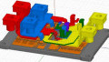
Figure 1. Hitachi Energy’s RoadPak. Image used courtesy of Bodo’s Power Systems [PDF]
When considering the complexity and quantity of components that must all function flawlessly for that engine to run as expected, the result is impressive evidence of outstanding engineering work over many years. This is typically based on a detailed analysis of possible errors, and many of these failure scenarios are tested in detail before market launch; therefore, their probability of occurrence is massively reduced.
With the introduction of electrically powered vehicles, the components that form the combustion engine have been replaced by electronic ones. However, the requirements for reliability and availability remain the same. Therefore, it is important to urgently address reliability, availability, and safety and present appropriate solutions that maintain performance in these areas.
Switching to electric motors is beneficial because electric locomotives have proven extremely reliable. An electric locomotive can cover several million kilometers over its lifetime, and electric vehicles may one day achieve something similar.
Although the knowledge gained in other applications of electric drive systems, such as electric locomotives, can be useful, the applications are different. For example, locomotives demonstrate relatively constant power with some peak power requirements after stops but, on balance, maintain a relatively stable load. Electric vehicles have many stops (e.g., at traffic lights or intersections) and must deal with varying speed limits, meaning power requirement changes frequently stop.
The differences in application are reflected in mission profiles, representing the power required by a vehicle over time in a specific use case. The profiles are slightly adjusted depending on the target audience. They can also include specific requirements, such as uphill starts with a trailer or high-speed acceleration for tests on racetracks. Individual use cases are based on frequency or mileage, and several such mission profiles result in a consolidated mission profile that considers multiple use cases. A typical time frame to achieve this is, for example, eight years and 400,000 kilometers.
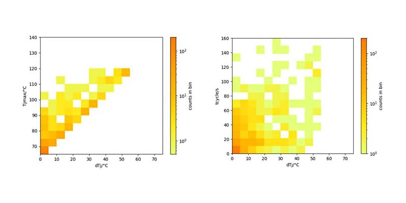
Figure 2. Analysis of 2 typical mission profiles of electric vehicles. Image used courtesy of Bodo’s Power Systems [PDF]
Although an attempt is made to cover all critical operating points, designers must remain realistic. Overloading the requirements will lead to over-dimensioning individual components, which can, in turn, result in unacceptable costs.
Important Semiconductor Parameters
From the consolidated mission profile, important parameters for power semiconductors, such as maximum junction temperature or the number of thermal cycles, can be deduced. The power semiconductor module can also be designed based on the mission profile, and the number of required SiC chips necessary to achieve the required performance can be determined. Ambient temperature (e.g., coolant temperature) is also considered. Furthermore, cycles profoundly influence the power semiconductor module design and the use of connection and bonding technologies. It quickly becomes apparent whether a conventional solder connection between certain components is sufficient or whether other connection technologies, such as silver sinter connections, a stronger bond that does not melt, are necessary.
The two illustrations provided each indicate the probability of occurrence (counts). The more orange visible in the diagrams, the more likely the case will occur. On the left, the likelihood of thermal changes in relation to junction temperature is plotted. Thermal changes in the high junction temperature range are much more critical and impact component lifespan. On the right, we see the dependence of thermal load cycles on thermal changes. Here, many cycles with large thermal load cycles are the challenge. The diversity is striking compared to the same analysis with locomotive mission profiles. The distribution of frequently occurring cases is spread across the entire spectrum and not consolidated into a few points.
AQG 324 makes a more concrete statement regarding mission profiles. It introduces load cycle tests divided into two different time ranges: PCsec with switch-on times of less than 5s and PCmin with switch-on times longer than 15 seconds. It is assumed that a thermally stable state is already reached after 15 seconds, especially for power semiconductors, so longer switch-on cycles do not result in additional heating. The test is defined as a failure test, and various parameters must be continuously monitored.
AQC 324 requires that the thermal resistance (Rth) should show an increase of less than 20%, while the increase in drain-source voltage (VDS)—or the reverse source-drain voltage (VSD) should be below 5%. Particularly in the PCmin test, the dependence of the change in thermal resistance, even to a small extent, on a change in source-drain voltage in MOSFETs presents a challenge. For example, an increase in Rth of <10% can lead to a 5% change in VSD. This is due to the strong relationship between the on-state resistance (RDSon) and temperature.
In these tests, it is important for a module with more than one logical switch (e.g., a half-bridge module or a module with six logical switches) that all logical switches are appropriately loaded and included in the assessment.
The junction temperature is an important parameter typically measured indirectly through the voltage drop across the body diode. Of course, this measurement is performed on both half-bridges, i.e., all logical switches.
Testing is time-consuming, as many (in the range of 100,000) cycles are expected. In the case of PCsec with 5s on-time and 5s off-time, this corresponds to 1,000,000s, equivalent to 12 days. For 1,000,000 cycles, it would be 116 days. It can also be expected that the number of cycles decreases as the junction temperature increases, i.e., a higher temperature difference between the junction and cooling temperature.
The behavior of Hitachi Energy’s RoadPak can be seen in the following table:
Table 1. Test results of Hitachi Energy’s RoadPak.
| Test type | ton / toff / s | ΔTj / K | Tj,max / °C | Avg. kcyc | End-of-Life (EoL) criteria |
| PCsec | 1.4 / 1.4 | 90 | 160 | >4,000 | N/A |
| PCsec | 1.4 / 1.4 | 105 | 175 | 848 | VSD increase |
| PCmin | 30 / 30 | 115 | 160 | 145 | VSD increase |
| PCmin | 30 / 30 | 130 | 160 | 62 | VSD increase |
In addition to the on/off time behavior (ton/toff), the previously mentioned temperature difference between the junction and cooling medium (ΔTj) and the maximum junction temperature reached (Tj,max) are shown in the table. To achieve meaningful results, the test must be conducted with multiple samples. In this case, six modules are used in parallel.
Understanding the Test Results
Understanding the significance of the results is very important. The larger the difference between the cooling medium and junction temperature, the smaller the values, which shortens the time required for the power semiconductor to successfully complete the specified cycles. This is well-known and understood in the field of silicon semiconductors. The dependence on ton/toff is also clear—the lower these times, the more cycles can be switched.
For electric vehicles designed for private use, PCsec cycles of 100,000-400,000 are required. For trucks, buses, and taxis, the value should be over 1,000,000 cycles. These values result from the vehicles’ different lifespans. The table results confirm that RoadPak meets the expected requirements for both private and public/commercial/industrial use.
This article originally appeared in Bodo’s Power Systems [PDF] magazine.