Facebook
 Google
 GitHub
 Linkedin
How Future Railway Converter Demands May Change Power Semiconductor Modules
The increase of competitiveness, robustness and efficiency of future railway converters has demanded new power semiconductor modules. Converter manufacturers particularly requested increasing power density and more flexibility for the converter design.
This flexibility shall be achieved by simpler parallel connection of power semiconductor modules, which leads to scalability of output power. This article presents the main challenges for power semiconductors in future railway converters and Mitsubishi Electric’s solution: power modules in the LV100 and HV100 package.
In 2015, a consortium of train manufacturers and electric equipment suppliers started discussions about the future of rolling stocks and radical innovations in the field of railway vehicles. The discussions, as part of the Horizon 2020 Project Roll2Rail, resulted also in technical requirements of tomorrow’s power semiconductor modules. These shall provide:
- Higher power density
- Multi-sourcing
- Modularity and scalability
- Readiness for SiC
- Ruggedness against environmental influences (temperature, humidity, vibration, …) [1]
Mitsubishi Electric’s answer to the requirements from the Roll2Rail project are the packages LV100 and HV100. Today, power modules in the LV100 and HV100 package have become available for various voltage and current ratings.

Figure 1. IGBT and diode chipset generations of MITSUBISHI ELECTRIC
The following article will introduce the silicon-based power modules of the LV100 and HV100 family. We will have a look at the advances in the chip and package technology, and measure the benefits in the application. A particular requirement of these power modules is the scalability of output power through the ability for parallel connection. The article will present a reference test setup for parallel connection and show the homogenous current distribution between paralleled modules for an optimal utilization of the silicon chip area.
Chip Technology
Mitsubishi Electric has long experience with manufacturing of the high voltage chips for railway application. The first products called H-Series addressed the entire voltage range from 1700 V to 6500 V. In the successional R-Series, the planar IGBT chip structure was optimized for lower forward voltage drop and improved device robustness. In the 1700 V class, N- and S-Series introduced the trench gate structure and CSTBTTM. The diode in the R-Series, N-Series and S-Series was optimized for better performance and softness. The recently developed X-Series utilize the CSTBTTM (III) technology for all voltage classes from 1700 V to 6500 V. The RFC (Relaxed Field Cathode) diode structure provides in the X-Series the balanced performance between low power losses and softness [2]. The maximum operation temperature is increased up to 150°C even for the 6500 V power modules.

Figure 2. Structure of X-Series IGBT-chip
The X-Series IGBT chip utilizes a lot of new features contributing to better module performance. The developed edge termination structure with LNFLR (Linearly-Narrowed Field Limiting Ring) allows active chip-area increase and thermal-resistance improvement. The SCC (Surface Charge Control) technology contributes to better humidity robustness [3]. The CSTBTTM (III) trench structure allows higher carrier concentration at the emitter side under on-state conditions. This reduces converter power losses by lower forward voltage of the device. The key criteria of the device selection in railway application is robustness. The partial P-collector in the edge termination region minimizes the hole injection and improve the robustness during turn off event.
Package Technology
The outside appearance and the new package is the most recognizable innovation of the new LV100-HV100 power module family. As shown in Figure 3, DC and AC terminals are located on opposite sides of the package. Hence, the DC capacitors with the low inductive busbar can be placed on the one side, whereas the AC load is connected from the other side. This allows clear separation of functional building blocks in the cabinet and easier converter design. The availability of three AC terminals ensures proper connection and high current-handling capability even for 1700 V voltage class or SiC power modules.


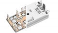
Figure 3. LV100 and HV100 packages for insulation voltage of 6 kV and 10.2 kV respectively

Figure 4. LV100 terminal layout with indication of the electrical potential (red: DC plus, blue: DC minus, yellow: AC) and available design space for the gate driver
The auxiliary terminals for the gate driver are located in between the DC and AC terminals. When several modules are connected in parallel, the intention is to have a large gate-driver PCB (printed circuit board) across all modules or multiple individual PCBs with short cable bridges in between. For sure, the location of gate drive terminals provides sufficient clearance and creepage distance even for parallel connected devices. At the same time however, the given layout offers maximal design space to our customers. Figure 4 shows the auxiliary terminal layout together with an indication of electrical potential by color. It is evident that the different potentials are well sorted. This allows easier insulation coordination, cheaper PCB material with lower CTI value and more design space for our customers’ gate drivers.
Another innovation of the LV100 and HV100 package is the MCB (Metal Casting direct Bonding) baseplate. As shown in Figure 5, it is an aluminum-based baseplate with AlN insulation and Al metallization integrated as single structure. Compared to a classical structure, the thermal resistance is decreased leading to increased power density and easier cooling. Moreover, the substrate solder, which usually degrades in the course of thermal cycling, is omitted with this MCB baseplate. The innovative MCB technology is utilized in both the LV100 and HV100 package ensuring 6 kV and 10.2 kV insulation voltage respectively.

Figure 5. Package structure of LV100 and HV100 package (illustrated at the LV100)

Figure 6. Improvement of power cycling capability of 3.3 kV HV100 in comparison to a previous generation 3.3 kV power module at respective nominal current
Besides electrical and thermal performance, also the robustness of the power module increases with the new package structure. Figure 6 shows the power cycling capability of the 3.3 kV / 600 A HV100 power modules (type name: CM600DE-66X). The figure compares it to a 3.3 kV power module with 10.2 kV insulation voltage of a previous generation. The numbers of cycles are given with respect to the power cycling capability at ΔTj = 80 K of the previous generation module. It is evident that the power cycling capability is increased drastically even though the maximal junction temperature has also been increased from 125°C to 150°C.
Parallel Connection
As mentioned in the introduction, the key requirement from the railway market for this new packages is the scalability. It allows for converter manufacturer to have flexibility at different projects to design the required output power. For example, by using the one, two or six CM600DA-66X modules, current ratings of 600 A, 1200 A or 3600 A can be achieved respectively.

Figure 7. Reference test setup for LV100 device evaluation (Source: [4])
The proper operation of the module in parallel connection is needed. Due to the fact of different converter designs, the railway manufacturers agreed on the reference test setup for evaluation of the parallel connection [4]. This reference setup, as depicted in Figure 7, allows evaluation of up to six paralleled modules. The design was done with the target to minimize the influence of the external parameters on the paralleling. Mitsubishi Electric uses the reference test setup for device switching evaluation. An example of two paralleled CM450DA-66X modules is shown in Figure 8. As a benefit, the railway manufacturer can get representative and comparable results that can be easily reproduced and verified. Moreover, Figure 8 shows perfect current distribution between two in-parallel connected LV100 power modules. Hence, optimal utilization of available silicon chip area is achieved.
Lineup Various products have already been developed by Mitsubishi Electric with standardized LV100 and HV100 packages. These products utilize the latest X-Series chip technology and cutting edge MCB baseplate. In LV100 package, 1700 V and 3300 V dual modules are available. Besides the 600 A version of 3300 V module also device with lower current rating of 450 A is available. Timely for PCIM 2021, the press release of 3300 V modules in HV100 modules has been published [5]. The modules with 4500V and 6500V voltage class are under development.

Figure 8. Turn-off of two CM450DA-66X in parallel using reference setup (Vcc = 1800V, Ic = 450A per module, Tj = 150°C)
Besides the available silicon-based dual power modules, Mitsubishi Electric has also developed the line-up of 3300V SiC power modules to fulfill the future demands of railway application in terms of efficiency and decarbonization. There are two current ratings of 750 A and 375 A available of Full-SiC version. Furthermore a Hybrid-SiC device with Si IGBT and SBD SiC diode with current rating of 600 A is available. It should be noted that SiC power modules use LV100 with special internal package structure. That structure is different from the silicon products, that have been explained in this article. Still, package outline and terminal locations are same.
Conclusion
This article has discussed requirements of future railway converters. The key points are increasing power density, higher flexibility and great robustness against environmental conditions. Mitsubishi Electric’s solution to these requirements are the LV100 and HV100 power modules. They provide higher power densities by latest XSeries chip generation and best-in class MCB baseplate. Flexibility is achieved by elaborate package design, auxiliary terminal placement and homogenous current sharing in parallel connection. Strong robustness is ensured by the X-Series chipset and newest package technology. In particular the SCC technology achieve highest robustness against high humidity conditions. The LV100 and HV100 power modules allow highly reliable, efficient and compact converters for railways - and other applications.
References
[1] T. Wiik, „D1.2, New generation power semiconductor, Common specification for traction and market analysis, technology roadmap, and value cost prediction,“ Roll2Rail , H2020 - 636032, 2016.
[2] N. Soltau, E. Wiesner, K. Hatori und H. Uemura, „X-Series RFC Diodes for Robust and Reliable Medium-Voltage Drives,“ Bodo's Power Systems, Nr. May, pp. 30-34, 2020.
[3] N. Tanaka, K. Ota, S. Iura, Y. Kusakabe, K. Nakamura, E. Wiesner und E. Thal, „Robust HVIGBT module design against high humidity,“ PCIM Europe, pp. 368-373, 2015.
[4] A. Nagel, J. Weigel, et. al., „Paralleling reference setup,“ Shift2Rail, Pinta, H2020 - 730668, 2019.
[5] Mitsubishi Electric Press Release No. 3389, Mitsubishi Electric to Launch HV100 dual-type X-Series HVIGBT Modules, Tokyo, Japan, Dec. 2020.
This article originally appeared in Bodo's Power Systems Magazine.
This article was co-authored by N. Soltau and E. Wiesner of Mitsubishi Electric Europe B.V. and R. Tsuda, K. Hatori and H. Uemura of Mitsubishi Electric Corporation.