 Facebook
 Google
 GitHub
 Linkedin
DC-DC Circuit Calculator
An inductor, which stores energy, limits the current slew rate through a power switch. The energy stored in the inductor can be expressed in joules as a function of the current with: E = 1/2 X L X I2
Equations & Topology
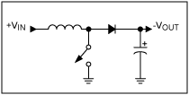
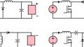
Figure 1. Simple boost converter
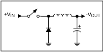
Figure 2. Buck converter topology
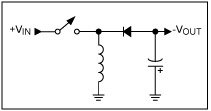
Figure 3. Inverting topology.
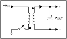
Figure 4. Transformer flyback topology.
The average voltage of an inductor over the switching cycle is zero in a steady-state operating condition. With this, when calculating for the boost circuit:
$$VIN X tON = tOFF X VL$$
And because:
$$VOUT = VIN + VL$$
We can then establish the relationship:
$$VOUT = VIN × (1 + tON/tOFF)$$
Using the relationship for duty cycle (D):
$$tON/(tON + tOFF) = D$$
Then for the boost circuit:
$$VOUT = VIN/(1-D)$$
Similar derivations can be made for the buck circuit:
$$VOUT = VIN × D$$
And for the inverter circuit (flyback):
$$VOUT = VIN × D/(1-D)$$
Application
Switching power supplies are more efficient than linear power supplies.


INPUT VOLTAGE 50-85V DC
INPUT CURRENT 2.5A
OUTPUT VOLTAGE(NO LOAD CONDITION) 13.5 ± 0.5V
OUTPUT CURRENT 7.5A
LOAD REGULATION 5%
PROTECTION OVER CURRENT,SHORT CIRCUIT
AMBIENT TEMPERATURE (-10 deg to 60 deg)
EMI/EMC AIS-004(PART-3) for this specification can i know which controller is relevant