 Facebook
 Google
 GitHub
 Linkedin
Damping Power Compensation in DC-Coupled Renewable Plants
A control branch for virtual synchronous generators adds damping during transient disturbances while leaving steady-state power-frequency behavior unchanged.
Wind farms, solar arrays, and battery systems increasingly share a common DC bus before a single inverter connects them to the grid. That DC-coupled architecture saves conversion stages, but it also means every gust of wind or passing cloud hits the DC-link capacitor first, then ripples into the power the inverter delivers to the grid.
Xinjiang University researchers have developed a method that suppresses transient power oscillations without altering how the inverter shares power or responds to frequency once the system settles. The researchers validated it in a 30 kW simulation and on a 2 kW hardware prototype.
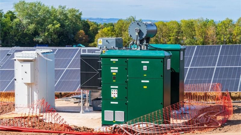
Solar inverter and transformer. Image used courtesy of Adobe Stock
Why Damping and Droop Collide in VSG Control
Conventional power systems lean on the rotating mass of synchronous generators to slow frequency changes after a disturbance. As inverter-based resources displace those machines, grids lose that inertia.
Most inverters today are grid-following; they lock onto an existing voltage and frequency and inject current accordingly. The U.S. National Laboratory of the Rockies notes that grid-following controls cannot guarantee stability in low-inertia settings, which is why grid-forming control, where the inverter sets its own voltage and frequency reference, has drawn so much research attention.
One popular grid-forming approach is the virtual synchronous generator (VSG), which emulates a machine's swing equation in software, complete with tunable virtual inertia and damping. According to the researchers, the catch in a standard VSG is that the virtual damping coefficient and the active-power droop coefficient combine into a single frequency-regulation term. Increasing damping to calm oscillations also changes the steady-state power-frequency characteristic, shifting how much power the inverter delivers for a given frequency deviation.
In a DC-coupled wind-PV-storage plant, that tradeoff is harder to escape. The DC-link capacitor absorbs source-side power mismatches, and the resulting voltage deviation couples back into grid-side active-power dynamics.
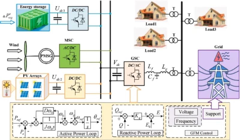
Overall control structure of the wind-PV-storage system. Image used courtesy of Cheng et al.
The Disappearing Compensation Path
In their study, the researchers added a compensation branch to the VSG active-power loop with zero steady-state gain. The branch low-pass filters the measured grid-side power and uses the difference between the instantaneous and filtered values as its input. During a transient, that difference is nonzero, and the branch adds damping. Once power settles, the difference returns to zero, and the branch does not affect the droop characteristic.
A second element, called the DC-link voltage-assisted compensation, applies the same gain to the DC-link voltage deviation. This lets the controller respond to source-side and grid-side disturbances together. The researchers state that earlier damping schemes based on active-power differentials are a special case of this broader structure.
This is notable because prior work has found limits to filter-based damping. For example, a 2021 IEEE Transactions on Power Electronics letter from Aalborg University researchers showed that a high-pass-filtered damping term in a VSG must keep its gain limited to preserve transient stability.
For their own scheme, the researchers derived a third-order small-signal model. Routh-Hurwitz analysis indicated asymptotic stability across the practical parameter range, and pole-locus analysis showed that higher compensation gain increases equivalent damping, while a small filter time constant keeps the added pole away from the imaginary axis.
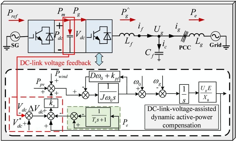
DC link voltage feedback. Image used courtesy of Cheng et al.
The study also lays out a step-by-step tuning procedure: choose virtual inertia first, then screen compensation parameters against damping, settling time, DC-link voltage limits, and measurement noise.
Simulation and Prototype Results
In the 30 kW simulation under combined wind-speed and irradiance disturbances, per-unit power overshoot fell from 0.20 with a conventional VSG to 0.02, a reduction of about 90%. Settling time dropped from 0.33 s to 0.08 s.
With a VSG with high fixed damping, overshoot dropped by about 75% and settling time was halved. For a 0.2 Hz grid-frequency step, overshoot fell from 0.11 to 0.05 and settling time from 0.37 s to 0.09 s. Compared with a competing transient damping scheme under the same step, overshoot was about 58% lower and settling time about 87% shorter.
The 2 kW prototype used a two-level grid-forming inverter with digital control. Under bidirectional active-power reference steps between 1.5 kW and 2.0 kW, overshoot was 0.04 per unit and settling time was 0.32 s, roughly 20% and 27% better, respectively, than an existing transient damping method. Under grid-frequency steps, peak deviation fell from 0.27 to 0.07 per unit (about 74%), and settling time from 1.27 s to 0.37 s. Steady-state error was zero at the reported precision in every tested case.
The researchers acknowledged that validation covered specific operating points and disturbance ranges. They also identified current and power limits, battery state of charge, DC-side nonlinearities, digital control delays, and interactions among multiple grid-forming converters as open questions for future work.
The study was published in Results in Engineering.