Facebook
 Google
 GitHub
 Linkedin
More Power by IGBT5 with XT
This article discusses the advantages of Infineon's 5th generation of 1700V IGBT with .XT technology and emitter controlled diode for inverter applications.
Enhanced power module performance with respect to the overall losses is an essential requirement to fulfill the continuous demand for inverters with higher power densities. The superior performance of the PrimePACK™ power module with the new generation 1700V IGBT5 and associated emitter controlled diode developed by Infineon Technologies AG addresses these application requirements.
The new 1700V IGBT5 and Emitter Controlled diode generation 5
Improvements in silicon performance are the basis to achieving higher power densities in modules used in inverter systems for a variety of applications. Wind turbines are one example where the desired power capacity per system has continuously increased. Compared to earlier generations, improvement in the 5th generation 1700V IGBT and the associated emitter controlled diode enable continuous operation at Tvjop = 175°C [1]. In spite of the higher thermal stress, power modules using these devices have strongly enhanced power density yet are rated for the same operating lifetime of the earlier generation. This is made possible through the use of the previously published .XT technology [2], which features high reliability for die-attach, Cu joint bonds instead of Al bonds, and improvements to the final system solder and alloy chemistry. Alternatively, if the power density is kept constant in comparison to earlier generation modules, the .XT technology significantly enhances the rated operating lifetime of the module.
1700V 5th generation IGBT
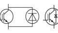
A schematic of the cross-section compared to the previous IGBT4 generation is depicted in Figure 1. Both devices are based on the successful trench-fieldstop technology. Furthermore, in order to handle the higher level of power dissipation during a short circuit event a thick copper (Cu) metallization on the front side is implemented. The success of this approach in increasing the short circuit withstand time was described at previous PCIM meetings [3, 4]. Additionally, the Cu-metallization is the enabler for the Cu-wire bonding implemented with the new .XT joining technology. The drawing also indicates a reduced active device thickness for the IGBT5 which results in decreased static and dynamic losses.

Figure 1: Schematic drawing of the cross section though a 1700V IGBT4 in comparison to the 1700V IGBT5

Figure 2: Output characteristic of the 1700V IGBT5-P5 compared to the 1700V IGBT4-P4 depicted at 25°C and their Tvjopmax for the same chip size
As with the previous technology generation, collector emitter saturation voltage (VCEsat) shows a positive temperature coefficient for the 5th generation IGBT (P5). Moreover, the improved vertical device concept results in significantly reduced on-state voltage for a same on-state voltage for the same chip size. This offers the opportunity to increase the current density in the same module footprint.
Besides the on-state losses the switching losses as well must be taken into account. A comparison of the static and dynamic losses of the 1700V P5 high power version with the corresponding 1700V P4, for a scenario where the current on the same PrimePACK™ module footprint is increased by 30%, is depicted in Table 1.

Table 1: Comparison of the per unit values for the P5 with the predecessor P4 on the same PrimePACK™ module footprint
Table 1 shows that even at 25K increased junction temperature, the 1700V IGBT5 has lower total switching losses per Ampere (Esw/A) compared to the previous generation device. Compared at the same junction temperature of 150°C, the IGBT5-P5, reveals the same VCEsat and more than 10% reduced total switching losses per ampere compared to the P4 in spite of the 30% higher nominal current.
One further important requirement that has to be considered in the evaluation of new IGBT technology is a suitably soft switching behavior, which provides EMI friendly operation. Figure 3 shows a turn-off curve measured for the new IGBT5 PrimePACK™ which was recorded at more than twice the nominal current and at room temperature where a very fast switching procedure is expected.

Figure 3: Turn-off curves of the PrimePACK™ module equipped with the new IGBT5-P5. More than twice the nominal current is handled at Tvj = 25°C
The turn-off curves impressively prove that the 1700V IGBT5-P5 achieved the design goal of providing a soft switching behavior in power modules with nominal currents up to 1800 A. This is in addition to the reduction of dynamic losses as listed in Table 1.

Figure 4: Schematic drawing of the cross section through a 5th generation 1700V emitter controlled diode in comparison with the previous generation device.
1700V 5th Generation Emitter Controlled Diode
For module design, maximum performance improvement for new generation power modules requires a power diode that is tightly matched to the IGBT. As illustrated in Figure 4, the 5th generation 1700V emitter controlled (EC) diode has been further reduced in silicon thickness compared to the former technology. This is the basis for the reduced stationary and dynamic losses.
Similar to the IGBT, the forward voltage (Vf) and reverse recovery losses (Erec) per Ampere match those within the previous diode generation. Silicon improvements also yield 30% higher current on the same PrimePACK™ module footprint and at 25 K increased junction temperature, just as with the IGBT5.
Despite the relatively huge reduction of the diode`s silicon thickness, the switching softness of the 5th generation device is very similar to its predecessor. This improvement was achieved by optimizing the field stop design of the diode. In Figure 5, the commutation characteristics of the two diode generations at 5% of the nominal current are compared. The measurements were performed at room temperature for the PrimePACK™ module equipped with 5th generation emitter controlled diodes.

Figure 5: Comparison of the commutation characteristics of the (a) 5th generation emitter controlled diode with (b) the 3rd generation emitter controlled diode.
To avoid a loss of surge current capability in spite of the 25K increased Tvj,op, the next generation diode also is equipped with a thick copper metallization on its front side [2] as illustrated in Figure 4.
Module performance – Inverter output current calculation
Based on this device-level data, an increase of the maximum inverter output current for the same module footprint using the new 1700V IGBT5-P5 is expected.
The IPOSIM simulation tool [5] from Infineon Technologies AG was used to verify this hypothesis. For the calculation, it was assumed that the silicon placement in a module with the PrimePACK™ 3 footprint remains the same. PrimePACK™ 1700V modules, introduced by Infineon in 2006, are a standard for power modules in megawatt wind mill applications. So the inverter output calculation considers the application in a generator-side wind power inverter.
≠For the calculation a liquid cooled system with an Rth,ha of 0.015 K/W per module arm and an ambient temperature of Ta=50 °C is anticipated. Furthermore, it is assumed that for this dedicated windmill application, the diode is typically the most relevant device for dimensioning the inverter. Therefore, a DC-link voltage of 1080 V, a base frequency of 15Hz, a modulation factor of 1.00 and a cos(φ) of -0.82 are assumed.
The results of the calculations are summarized in Figure 6. Achievable inverter output current is plotted as a function of the switching frequency. The black and blue curves depict the current calculated for the 5th generation devices and the 4th generation devices at Tvj,op = 150°C. The red curve denotes the maximum achievable inverter output current for the IGBT5 at TvjopMax = 175°C.

Figure 6: Improvement in inverter output current when replacing IGBT4 with IGBT5, allowing up to 175°C junction temperature
The simulation results indicate that the maximum inverter output current can be increased by approximately 30% using of the new 5th generation technology. The blue curve represents the maximum output current calculated for the 5th generation module when Tvj,op is limited to 150°C. Under these conditions, the .XT internal module packaging technology improves module lifetime by 10% and the maximum achievable output current is still increased by approximately 10%.
Summary
The 5th generation 1700V IGBT and emitter controlled diode from Infineon Technologies are designed to operate at Tvj,op = 175°C. The increased usable operating temperature enables a massive increase in power density for the well-established 1700V PrimePACK™ module platform. Utilizing the .XT technology, these new PrimePACK™ power modules fulfill the harshest requirements, lifetime and surge current events, as well as EMI friendly operation. Alternatively, the .XT advantage can be employed to enable an unprecedented enhancement of the lifetime along with a moderate increase in power density.
About the Authors
Wilhelm Rusche works as the Technical Marketing - High Power Innovation at Infineon since October 2014 where he is responsible for the definition and specification of new products in power electronics. He is a Graduate Engineer in Electrical Engineering at the Comprehensive University Paderborn Dept. FH Meschede.
André Stegner worked as the Manager of Research and Development at Infineon Technologies. Now, he works as the Director of Research and Development since February 2019 where he is responsible for the director chips and discrete development in the field of power semiconductors. He holds a Diploma and a Doctorate in Physics earned both at the Technical University of Munich.
References
- A. Stegner, et al., Next generation 1700V IGBT and emitter controlled diode with .XT technology, PCIM, Nuremberg, Germany, 2014
- A. Ciliox, et al., New module generation for higher lifetime, PCIM, Nuremberg, Germany, 2010.
- A. Ciliox, et al., Next step towards higher power density with new IGBT and diode generation and influence on inverter design, PCIM, Nuremberg, Germany, 2012.
- F. Hille, et al., Failure mechanism and improvement potential of IGBT’s short circuit operation, Proc. ISPSD 2010, Hiroshima, Japan, 2010.
- IPOSIM: IGBT Power Simulation, available at www.infineon.com
This article originally appeared in the Bodo’s Power Systems magazine.