Facebook
 Google
 GitHub
 Linkedin
The Influence of IGBT5 and .XT Technology on the System Power Density illustrated through a Hardware Demonstrator
This article discusses the advantages brought about by IGBT5 and .XT Technology in increasing the power density and lifetime of power modules.
At present increase in power density and enhancement of lifetime of the power modules are limited by the chip and inter-connection technologies. ‘IGBT5 and .XT’ technology is based on the idea to develop a solution which will lead to an increase in the module power density along with lifetime improvement.
This new technology improves the power cycling (PC) capability of the power modules. The improved PC capability can be used in two different ways: firstly, to enhance the lifetime of the module. Secondly, to use PC enhancement for an increased power density by means of an increased maximum operational junction temperature. In this article, the influence of ‘IGBT5 and .XT’ technology on the system power density is illustrated through a hardware demonstrator.
IGBT5 and .XT – Module Power Density vs Lifetime Trade-off
Figure 1 depicts the power density vs lifetime trade-off triangle. The enhancement of the lifetime of the new 5th generation module corresponds to the movement in the horizontal direction in Figure 1 (along the x-axis). An increased module power density is enabled through an increased maximum operational junction temperature. In Figure 1, this corresponds to the movement in the vertical direction (along the y-axis) with respect to existing solution.
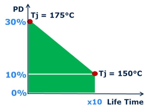
Figure 1: Power density and lifetime trade-off curve for ‘IGBT5 and .XT’ at the same chip size
IGBT5 and .XT in PrimePACK™ Package
The PrimePACK™ 3 power module housing introduced in 2006 has become a standard for power module housing in the megawatt power range. Owing to its success it is self-evident that the launch of the new 5th generation 1700 V IGBT will take place in the PrimePACK 3+ housing [1-4]. At present, the maximum available current rating in the PrimePACK 3 housing in a half-bridge configuration is 1400 A.
With the introduction of this new 5th generation IGBT half-bridge module together with new .XT interconnection technology, the nominal current rating of the module increases to 1800 A. To enable this increase in module current, the present PrimePACK 3 package is modified. It now contains two AC bus bar and terminals instead of one AC. The general outer dimensions of PrimePACK 3 package are retained with only a small modification.
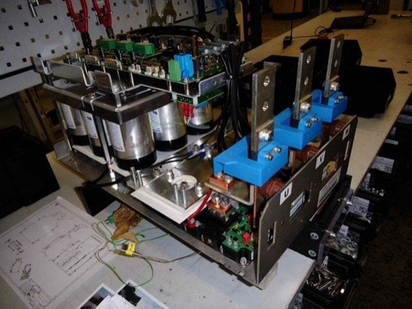
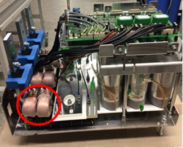
Figure 2: Photo of the two demonstrator stacks built: (top) Stack with FF1400R17IP4, (bottom) Stack with FF1800R17IP5
Module Power Density vs System power density
The percentage increase in module’s power density may not translate directly into system power density. The best way to determine the influence of module power density on the system power density is to build two demonstrators, one with existing IGBT4 power module (FF1400R17IP4) and another with new 5th generation module (FF1800R17IP5) and compare the system power density of both. The two demonstrators were built on an Infineon STACK platform as shown in Figure 2.
The main difference between the two demonstrators is that the FF1800R17IP5 features two output AC terminals instead of a single one. In the newly built demonstrator, the additional AC terminal has been taken into consideration and the mechanical construction of the system is adapted accordingly. This arrangement is explicitly marked with a circle as depicted in Fig. 2(right). This mechanical adaptation leads to a change in the length of IGBT5 based STACK thereby leading to a change in the system volume. It should be noted, however, that the PrimePACK 3 and the new PrimePACK 3+ have the same module footprint (HxWxL = 38x89x250 mm).
Each hardware demonstrator consists of a 3-phase inverter having one module in each phase. The DC link consists of a 3.6 mF DC bus capacitor and the output AC terminals of the demonstrator have three Hall-effect current sensors.
Table 1 lists the important parameters of the demonstrator developed.
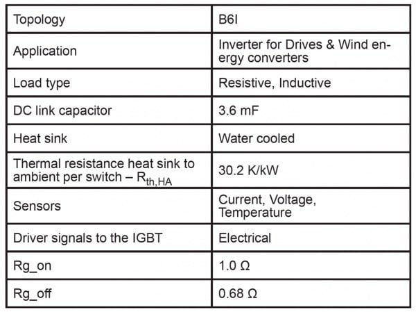
Table 1: Important parameters of the demonstrator
A summary of the change in system volume is pictorially depicted in Figure 3 and listed in Table 2
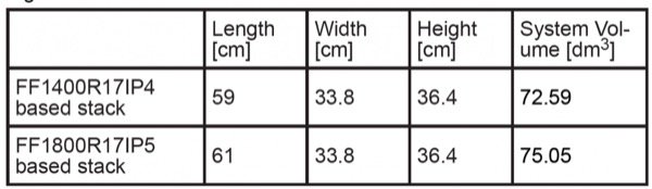
Table 2: Dimensions and system volume for FF1400R17IP4 and FF1800R17IP5 based Stacks
To obtain the system power density at conditions which are relevant and typical for the application, the two stacks were tested according to the parameters as listed in Table 3.
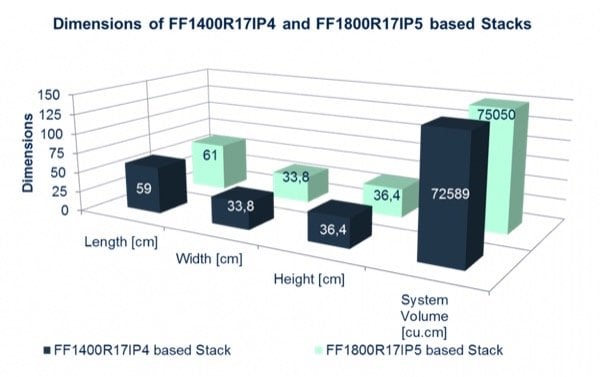
Figure 3: Dimensions of FF1400R17IP4 and FF1800R17IP5 Stacks
Both stacks were tested under identical output voltage and power factor conditions. Therefore, in such cases, the system power density is simply related to the output current and system volume. For example, if the output voltage and power factor is 690 V and 1.0 respectively, then the system power density is as listed in Table 4.
Increase in system power density of an IGBT5 based stack compared to an IGBT4 based stack is 26.5% as shown in Figure 4. For a detailed temperature profile of the stacks under above mentioned operating condition refer to [1].
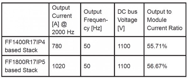
Table 3: Test conditions for the two stacks
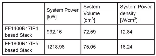
Table 4: Comparison of system power density
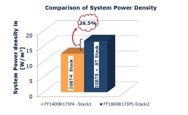
Figure 4: Comparison of system power density of IGBT4 and IGBT5 Stack
Conclusion
An increase in power density and lifetime of the power modules are enabled by IGBT5 and .XT technology. For nearly the same output current to module current ratio of both the demonstrators, the IGBT5 and .XT technology based power stack leads to an increase in system power density of 26.5% compared to IGBT4 based stack with no change in module footprint (HxWxL = 38x89x250 mm) between PrimePACK™ 3 and the new PrimePACK 3+ package.
About the Authors
Dr. Raghavan Nagarajan works as the Technical Manager System Engineering at Infineon Technologies AG since April 2013. He holds a Bachelor's Degree in Electrical and Electronics Engineering, Master's Degree in Power System Engineering and Doctorate Degree in Electrical Engineering.
Hubert Kerstin works as the Marketing Director at Infineon Technologies AG, a German semiconductor manufacturer founded in 1999 that markets semiconductors and systems for automotive, industrial, and multimarket sectors, as well as chip card and security products.
References
- Raghavan Nagarajan and Dirk Brieke: Aspects of increased power density with the new 5th generation IGBT demonstrated by application relevant measurements, PCIM, Nuremberg, Germany, 2015.
- K. Guth et al.: New assembly and interconnects beyond sintering methods, PCIM, Nuremberg, Germany, 2010.
- M. Schulz: Power Semiconductor Development, Bodo’s Power Systems, February 2015.
- Andre R. Stegner et al: Next generation 1700V IGBT and emitter controlled diode with .XT technology, PCIM, Nuremberg, Germany, 2014.
This article originally appeared in the Bodo’s Power Systems magazine.